Thursday, July 23, 2015

Douglas AD (A-1) Skyraider Pylons

The configuration and orientation of Skyraider weapons pylons comes up from time to time. They are usually not depicted correctly in model kits. This is a work in progress.

The pylon on the inboard wing was perpendicular, i.e. hanging straight down (except on the unique pylon for the big podded radar: see http://tailhooktopics.blogspot.com/2012/11/ad-4n-aps-31-radar-pod.html). The pylons on the outboard wing panel were perpendicular to the wing instead; they were also not evenly spaced.
The view from the side showing the longitudinal spacing of the outboard pylons.

As shown here, the outboard wing pylons were not "swept" at the same angle as the leading edge, i.e. the most outboard one was closer to the wing leading edge than the most inboard.

The external center-line pylon was introduced with the AD-4B and carried forward to the AD-5/6/7:

Note the interface with the oil cooler outlet: the forward end of the pylon is much deeper because it sweeps up into the duct (don't be mislead by the shadow).
 I'm told that the Trumpeter 1/32 center pylon does not angle upward from front to rear as it should.

Early ADs had much smaller and less capable AERO pylons on the outboard wing panel. See http://tailhooktopics.blogspot.com/2013/12/things-under-wings-aero-pylons.html

AD-1s through -4s had a smaller inboard wing pylon than the 5/6/7. The later, longer pylon introduced on the -5 was reportedly necessary to move certain stores farther forward for ground clearance. It also added provisions for the 30-inch lug spacing required for some stores. In addition, it may have been desirable to move the loaded center of gravity forward, particularly on the -5.
Thanks to Ed Barthelmes for a pretty good drawing of the early pylon. However, it has been hard to pin down the exact location of the early pylon on the wing from available drawings. The above drawing is my best guess at the moment.

Here is a direct comparison of the World War II era 1,000 and 2,000 lb bombs on the earlier pylon (note that the 2,000-lb bomb had 30-in lugs and therefore had to be attached with an adapter).
As noted above, ADs before the -4B/5/6/7 did not have an external center pylon. The shackle was mounted within the fuselage along with provisions for an explosive-cartridge actuated "foot" that propelled the bomb downward away from the airplane when dive bombing so that it would not hit the propeller.
 
Illustration from Ed Barthelmes

As a result, the bomb or torpedo was snugged up directly beneath the fuselage.
U.S. Navy via Steve Ginter

Wednesday, July 15, 2015

F6F-5K Drone Strike, Korea

For background on this and the F6F drone program in general, see http://tailspintopics.blogspot.com/2009/11/f6f-drones.html.


Note that the bomb has not tail fins (it's not going to be dropped), the F6F does not have the F6F-5K tailwheel extension (it's not coming back), and the additional antennas for remote control and television picture transmission.

Saturday, May 16, 2015

Special Hobby AF Question

A question was raised about the length of the cowling based on a photograph of a Grumman AF model built from the recently released Special Hobby 1/48th kit, specifically whether it looked a little short. (http://www.britmodeller.com/forums/index.php?/topic/234981898-new-148-grumman-guardian-by-special-hobby/)

Based on a pretty good Grumman three-view, which compared quite well to the Grumman fuselage station data, I calculated that the distance between the leading edge of the wing at the fuselage and the forward edge of the cowling at the fuselage reference line (where the propeller shaft extends), should be 69 mm or about 2 3/4 inches. The kit dimension was subsequently reported to be 65-66 mm.

At that point, I double checked my scaling of the fuselage station drawing (good only for length, not shape, particularly the vertical fin in this instance) and the Grumman three-view and added the AF Standard Aircraft Characteristics side view for comparison. All the drawings compared well in length, with the clear exception being that the wing on the SAC side view was about 3 mm farther forward than on the other two drawings.


I cropped the above to illustrate the difference between the SAC wing location and that of the other two drawings.
It's possible that Special Hobby relied on the SAC sideview for the wing location.

The perceived discrepancy in the picture of the model is likely exaggerated by the camera.

Wednesday, April 29, 2015

ESCI 1/48th FJ-2/3

29 October 2016: It turns out that I was wrong about being wrong with respect to the FJ-4 horizontal tail so I revised the top view drawing at the bottom of this post. Thanks to maintenance manual data provided by Frank Truchi, a volunteer at the National Naval Aviation Museum, I now know that the production FJ-4 horizontal tail leading edge was swept at 35°. The NAA drawing of the horizontal tail is therefore accurate except for the span.  (Also see http://tailspintopics.blogspot.com/2016/10/north-american-fj-44b-fury-notes.html.)

Some people are desperate for a good injection-molded kit of the North American FJ-2/3 Fury, so desperate that they consider building the ESCI 1/48th kit. While I'm sure that a fairly accurate model can be built from it, some changes will be necessary.

The most notable errors are in the forward fuselage,
as detailed here:
Note that the ejection seat is located too low and far aft in the cockpit.

It fairs even worse as an FJ-3, because its inlet was even deeper. (And that scoop on the aft fuselage needs to be cut down and a recessed ramp added ahead of it.)
Note that the aft nose landing gear door is not wide enough.

Since the bottom of the sliding canopy has the distinctive "dip" of the FJ-2/3's at its forward end (added to allow the pilot to sit higher for takeoff and landing while closing and opening the canopy) and the inlet is an undersized version of the FJ-2's, it doesn't make for a good XFJ-2 out of the box either. The XFJ-2 had the standard F-86 sliding canopy with a modified windscreen for better over-the-nose visibility. For an overview of the North American FJ Fury family, see http://tailspintopics.blogspot.com/2009/10/fj-fury.html

However, even given its shortcomings, the kit has possibilities. Deepening the forward fuselage wouldn't be too difficult. "Impatient Pete" modified an F-86 with this cut on the way to an FJ Fury in an ARC forums post.

The bottom of the windscreen and sliding canopy could possibly be filed down to lower them to the right height. A F-86 canopy might be even better.

I don't have the kit so I can't say what has to be done to the wings, horizontal stabilizer, etc to improve its accuracy. For those details, see http://tailspintopics.blogspot.com/2011/04/fj23-fury-redux.html

While most of us are content to imagine the possibilities or hope for a new FJ-3 kit, Jon Kunac-Tabinor has not only sallied forth with the Esci kit, he is posting his progress here: http://www.britmodeller.com/forums/index.php?/topic/234981173-north-american-fj-3-fury-148th-esci-with-added-elbow-grease/#

However, Jon is having trouble with the quality of Esci plastic and Bob Sikkel reports that the Esci wing has the incorrect sweep and aileron location. The desperate might want to consider another 1/48th scale alternative, a mash up of the Grand Phoenix FJ-4 and a Monogram F-86.  The FJ-4's fuselage was very similar to the FJ-3's (see Jon Krol's comments below and the following illustrations). Bob Sikkel also provided the following comparison of 1/48th kit inlets to which I've added photographs of the actual airplanes.
Somebody has measured the FJ-4 at Tyler, Texas as having an inlet width and height at the location of the inlet plug of 23".

The FJ-3 and FJ-4 fuselages were almost identical, except of course where it is obvious that they aren't as well as the small difference in downward angle of the 20 mm guns. While the main landing gear was very different, the nose gear appeared to be the same except that the shock strut was more extended at rest.
Note that the North American draftsman had to wing it with details like access panels, speed brakes, etc. (obvious when comparing the FJ-3 and FJ-4 side views) so there may be some variation in their location from the above. Your guess is as good as mine on the vertical fin: were the leading and trailing edges different or not?

The wings and horizontal tails were very different, which is where an F-86 kit is required.


Note the difference in span between the prototype and production FJ-4 horizontal tails:

Friday, April 17, 2015

Cockpits

A work in progress:

Before World War II, Navy carrier-based airplane cockpits were painted with aluminum lacquer or interior green except for the instrument panel, side consoles, and radio equipment. This is the cockpit of the one and only XF4U-1 (your guess is as good as mine as to the color of the light areas):


Interior Green became the preferred color for the cockpit structure early in the war (less reflective) but at some point during the war and before March 1954 (see http://www.ipmsstockholm.org/magazine/2004/05/stuff_eng_interior_colours_us_part3.htm), the cockpits of Navy carrier-based airplanes were to be semigloss Black from the level of the bottom of the instrument panel and the top of the side consoles and nonspecular Interior Green below. Ejection seats were usually interior green. After this, the cockpits were to be Dark Gull Gray (DGG)  with black instruments and consoles. Ejection seats were either black or DGG as will be discussed. Of course, the basic changeover from black cockpits to DDG ones took time and the devil is in the details. It also did not correspond directly with the change in the exterior paint scheme from overall blue to gray/white, which was decreed in February 1955, almost a year later. For more on that, see http://tailspintopics.blogspot.com/2009/12/changing-from-blue-to-graywhite.html.

BuAer color specifications often left room for interpretation or to paraphrase Captain Barbossa, are "more of what you'd call guidelines than actual rules". For example, did painting the console black refer only to its top or also to its sides? A company would incorporate its interpretation of the spec in its manufacturing documents, which were incorporated by reference in its production or spares contract with the Navy. The aircraft would subsequently go through repair and overhaul at a Navy facility every few years (sooner if it was badly damaged in an accident but considered repairable); the painting instructions at the Navy facility were not necessarily the same as the manufacturer's. As a result, the wheel wells on blue airplanes might be painted zinc chromate when it was delivered but the repair and overhaul facility would paint them blue. Also see http://tailspintopics.blogspot.com/2012/10/painting-crush-points-red.html

Basic Black

AD-4 Skyraider:  The floor is not obviously Interior Green but the lower section of the control stick appears to be. Note that the instrument faces are a darker black than the instrument panel itself.

FJ-1 Fury: This is a National Air and Space Museum photo of a restoration (I'm not sure that it was one of theirs).

F9F Panther: This is another restoration but it appears to be fairly accurate. Note that the seat is interior green. However, in service, it would have a seat cushion or parachute in the bucket. If the seat was designed for a backpack parachute, it would be in the seat. Carrier pilots did not wear their parachutes to and from the airplane due to the consequences of it inadvertently being deployed.

F7U-3 Cutlass: This is the cockpit of the F7U-3 being restored at Paine Field, Washington. It appears to be original. Note that it is almost completely black except for the control column.


The ejection seat was Interior Green.

For more on the F7U cockpit and a caution on using museum airplanes for reference, see http://tailspintopics.blogspot.com/2012/12/cockpit-confusion.html

For some reason, North American FJ-2 Furys and at least some FJ-3s were delivered with cockpits in a very different shade of green, including the ejection seats.


Although the change in the specification to Dark Gull Gray was issued in early 1954, this Naval Aviation News article on cockpit colors appeared in the January 1957 issue, about a year and a half later given publishing lead time.

Note that it mentions light green instrument panels, which might be the case with the FJ-2/3 as discussed above.

For more on the FJ-2/3 "green" cockpit, see http://tailspintopics.blogspot.com/2021/08/north-american-fj-23-cockpit-and.html

Basic Grey

The basic black cockpit was eventually faulted as being too dark. After some experimentation, the specification was revised to change the instrument panel to dark gull gray along with the sides of the consoles and the floors. This FJ-4 cockpit (not a museum airplane) is an example.


 There was subsequently some variation in the color of the ejection seats in the gray/white airplanes. Douglas installed black ejection seats even in blue airplanes and initially in F4Ds since the color of the seat was not initially specified as part of the change from overall blue.

In May 1963, the Navy finally decreed that ejection seats be dark gull gray.
However, Grumman painted the headrest of some seats black and of course, all Martin Baker seats are overall black.

Friday, March 27, 2015

TBU/TBY Wing Fold

Somebody asked for details on the TBU/TBY wing fold area because it isn't covered in detail in Steve Ginter's monograph. Note that there are two hinge points, one on the main spar and one on the forward spar, and a large bellcrank that is driven by two actuators, one in the inboard wing and the other in the outer.

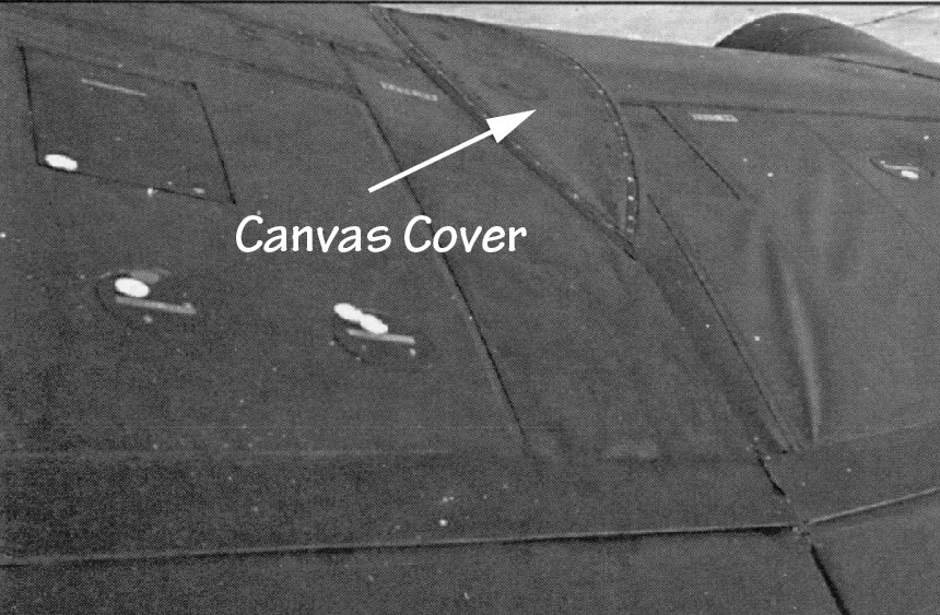
There was one confusing element, an oval panel with pointed ends on the upper surface of the wing over the wing-fold area. The panel was necessary to provide an opening for the outer wing to fold past vertical.

I initially assumed that the panel was metal and part of the outer wing but I couldn't figure out how it didn't interfer with the hinge on the main spar. I finally realized that it was something like canvas (perhaps a rubberized fabric) and simply folded in on itself.

Here the cover appears to be bulging upward from aerodynamic pressure in flight.

This illustration shows the location of the main spar hinge relative to the forward hinge point and the cover

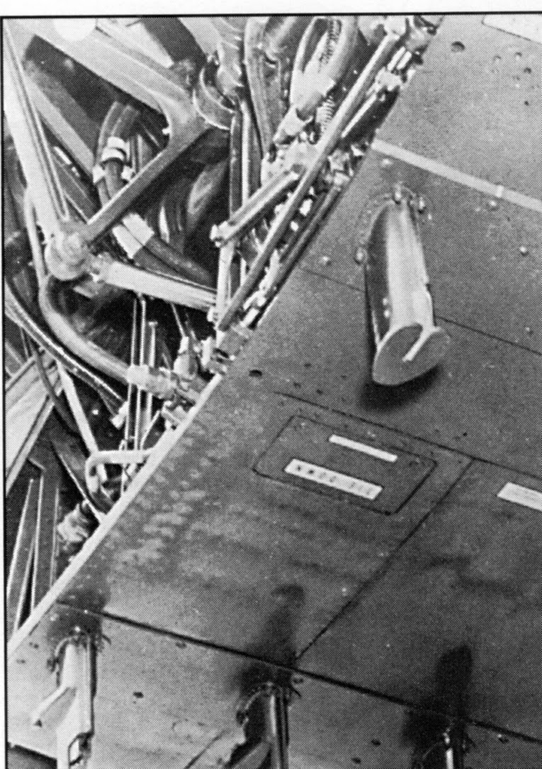
This was the only other picture that I could find of the fold area. It shows the lower half of the wing-fold actuator bellcrank and the inboard actuator.

Monday, March 9, 2015

F8U Underwing Details

There isn't much to be seen under the wing of an F8U when it is raised, even the underside of the wing itself.

Note that there was only one actuator to raise and lower the wing (the F8U-3 had two).

The top of the fuselage can barely be seen although this is what it looks like with the wing removed, looking forward from the pivot point.
There's a lot of white overspray on this derelict fuselage. The forward bulkhead should be red. The duct on the right side is covered with a silver insulation. Some of the piping was green zinc chromate. There is also a red fuel filter or something along the right forward side.

Tom Weinel has done some research and concluded that the area was green up through the early 1960s (e.g. F-8Es) and then painted white during Navy overhaul at some point or when the F-8s were rebuilt by Vought.