Sunday, September 12, 2021

TBF-1 versus TBM-3 OIl Cooler Location

 16 September 2021: Bill Spidle spotted the faint lines of the TBF oil cooler duct that I missed on the powerplant installation illustration.

First, note the different cowls of the TBF-1 and TBM-3:

In both instances, the upper air inlet only provided air to a downdraft carburetor aft of the engine. Another inlet was added to the bottom of the cowl on the TBM-3 to provide air directly to a single oil cooler mounted at the bottom of the engine nacelle. After passing through it, the air exhausts out the bottom of the cowling through a flap similar to a cowl flap.

The TBF-1 had two oil coolers, one on each side, exhausting through doors on each side of the forward fuselage.

There appears to be a duct in the engine compartment leading to the oil cooler with its forward end behind the aft row of engine cylinders:

You have to look closely to see the lines representing the duct leading to the oil cooler (item 150) and its forward opening in this illustration:

 Note that it is routed above the hot exhaust collector (item 149).

However, it does seem like a poor way to provide air to the oil cooler, given that it's being taken from a hot engine compartment, but there doesn't seem to be any room between the cylinder heads and the side of the cowling for the duct to extend forward.

And perhaps that's why the TBM-3 powerplant installation was revised to provide an air inlet at the bottom of the cowl:

That relocation resulted in a change to the cowl flap configuration (those provide the exit for air in the engine compartment at low speeds and high power settings to increase the air flow over the hot engine cylinders).

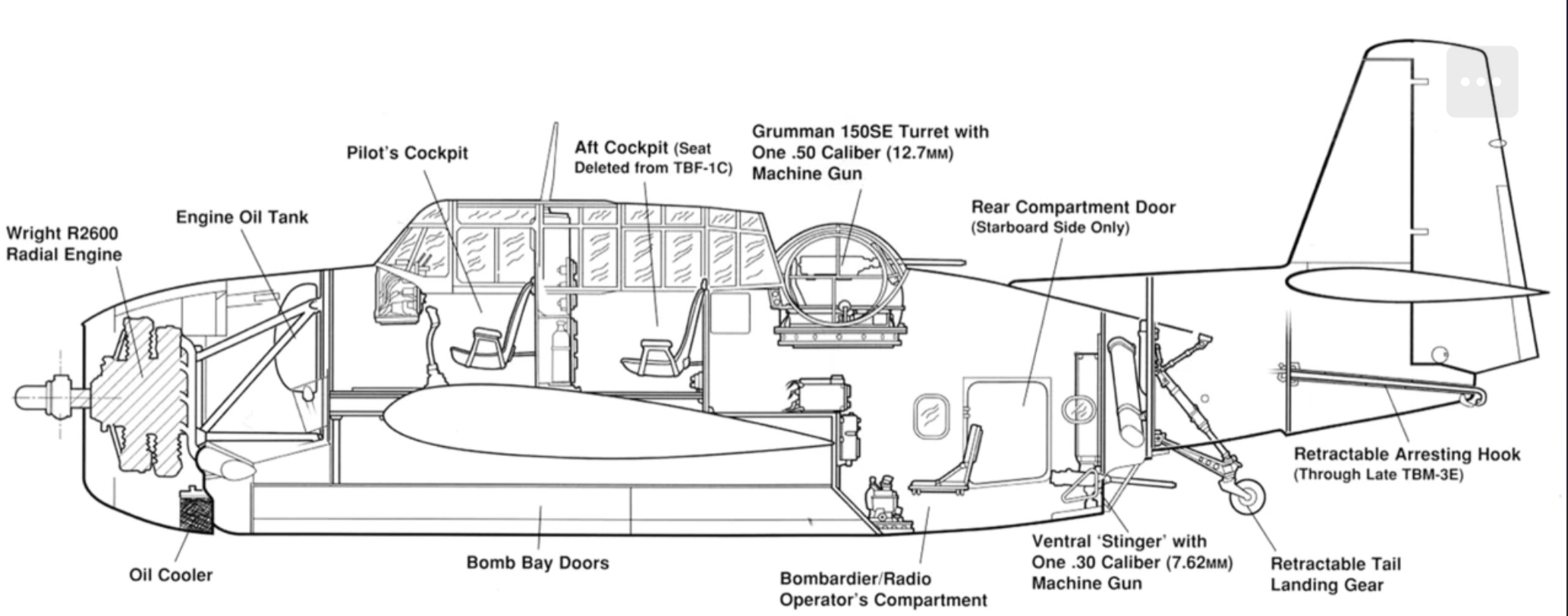
This inboard profile adds to any confusion:

It appears to be intended to show the early TBF configuration but the oil cooler location is the later one.


Sunday, August 8, 2021

North American RA-5C Flasher Pod

14 August 2021: Jerry Wells provided me with maintenance manual details that required a slight revision to the drawing

 9 August 2021: I should have checked with Boom Powell before I posted this...

For night photography, the RA-5C could be fitted with a self-powered flasher pod, part of the LS-43AI "Flasher System Photographic, Aircraft".

A propeller was mounted on the aft end of the pod to provide the power required for the electronic flash. Flares had previously been used by the Navy but the technology dated back to World War II: https://invention.si.edu/seeing-dark-aerial-reconnaissance-wwii

From Vigilante!

"The pod had three strobe lamps, powered by the air stream, which generated 3 million candlepower in a 43-degree cone of illumination. The flasher pods could be set to flash either together or alternately, depending on the altitude and speed of the aircraft. The alternate mode gave each pod more time to recharge and therefore a brighter flash. The maximum usable altitude was 3,500 feet above the ground... The NATOPS Manual warned (because of the 2,600-volt capacitors), 'Do not touch for 10 minutes after power off' and 'Flasher can inflict PERMANENT BLINDNESS' ".

I created this drawing from odds and ends of documentation as well as photographs not well suited to the task but I think it will be adequate as a modeling reference (note: Rev A corrects the shape of the small cooling air inlet at the front of the pod; Rev B corrects the aft end of the pylon where it attaches to the wing). Unlike other air-driven ECM/IFR pods, the generator was turned by a propeller with only two blades.

The pod could be mounted under either wing:

This picture should suffice for a cross section:

Boom Powell Collection

Sunday, June 6, 2021

Grumman F9F-8P Photoflash Cartridge Ejector Pylon

ReccePhreak asked about the F9F-8P's photoflash pod needed for night aerial photography. The answer turned out to be hidden in plain sight and it wasn't a pod but more of a pylon. It isn't identified on the F9F-8P SAC three-view but it's there at Wing Station 96, 25 inches outboard of the pylon used for external tanks and just outboard of the wing fence:

I also found two pictures of it on the wing in Steve Ginter's Naval Fighters Number Sixty-Seven, Grumman F9F-6P/8P Photo-Cougar:


And another, not mounted, in my files:

Note that it's about twice the width and depth of the inboard pylon. Jerry Wells then provided me with technical manual information for the F9F-8P and F2H-2P that included a description of the two different flash-cartridge holders and this isometric cutaway illustration of the F9F-8P Mk 51 Mod 14 pylon.

That allowed me to create this notional drawing of the pylon (Butt Line is the same as Wing Station):

Note that the Ejector Type A-6 contains 52 flash cartridges and the B-4, 20 somewhat larger ones.

The F2H-2P did utilize a pod that incorporated the A-6 and B-4 cartridge holders for night photography.


This is my notional illustration of that pod.

One point of confusion is that the F2H technical manual was explicit about a pod with the B-4 ejector being loaded on station 7 only but the 20-cartridge pod in the picture above my drawing is mounted on Station 2 (the eight pylons are numbered from left to right).

Note that the pod in both pictures appears to be mounted on the outboard F2H pylon (station 1/8) that was located farther forward than the next one inboard but that's because a fairing was added on the front of the AERO 14 pylon at station 2/7 to cover the wiring added to control the flash cartridge deployment.

For more on the F2H pylon installation, see http://tailspintopics.blogspot.com/2021/06/mcdonnell-f2h-banshee-stores-pylons.html


Wednesday, February 24, 2021

Westinghouse J40 Afterburner Nozzle

 Afterburning requires a variable exit nozzle that increases the size of the opening for the increased thrust. The nozzle was often fully open during engine start to reduce back pressure and also at idle, to reduce idle thrust.

Afrerburner nozzles now are generally fully variable (or can at least be partially opened in one or more positions) but back in the day in part due to fuel control limitations, were either fully open or fully closed.

Hence the acceptability of a clam-shell nozzle, which is what Westinghouse utilized on the J40:

This is a picture of the rear end of a J40 with the outer shell around the clam-shell halves cut away from 9 to 12 o'clock like the rest of the afterburner section:

Note that the nozzle is fully opened and located between an outer shell and the tailpipe. Also note the flame-holder rings that fed fuel into the afterburner. I'm sure that the interior of the afterburner was not red; it was just painted red on this display engine to differentiate it from the other engine sections.

I don't have a good picture that shows the gap between the two halves of the clam-shell nozzle when it is fully open but this should give you the idea:

The actuator housing was the reason for that small fairing on the side of the fuselage. The natural metal surface is fuselage skin. Aft of that is the dark outer shell of the engine itself and aft of that are the open clam-shell halves.