Tuesday, December 30, 2014

F9F-8 Variations

Kitty Hawk is shipping its 1/48th F9F-8/8P kit:

For the Cybermodeler in-box review, see http://www.cybermodeler.com/hobby/kits/kh/kit_kh_80127.shtml

Paul Boyer has built one for a modeling review (note that Kitty Hawk did not fix the flat nose strut from its F9F-8T kit; Paul modified it to give his Cougar model the correct sit):

He also only folded one wing to illustrate the kit option and notes that it sits at an angle (it's hard to tell from a photo if it's the correct angle for an F9F-8, which was 80 degrees):

Note that there should only be a clear window for the approach light (an angle of attack indicator) in the left inner wing leading edge. Like the deflated nose strut, this error was carried over from the Kitty Hawk F9F-8T.

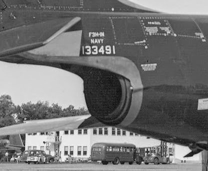
One of the questions that has arisen is the effectivity of the inlet splitter plate. This was a prominent feature added at some point during the production run to improve performance.

After looking at lots of pictures, my guess is that it was incorporated at some point between BuNo 141157 (no splitter plate) and 141172 (splitter plate) and was not retrofitted to earlier Cougars except for at least two -8s that were used for Grumman flight test. (The F9F-8Ps and F9F-8Ts were all produced with splitter plates.)

With two exceptions, I've not seen a picture of a overall-blue Cougar with the splitter plate. One is BuNo 131894, which appears to be dedicated to test, and the other is the sole Blue Angels' single-seat F9F-8 with a splitter plate, BuNo 144279 (it also had the mounting point for the inflight refueling probe).

Early gray/white F9F-8s did not have the splitter plate. Another exception to BuNo 141157 or earlier not having it is BuNo 141140, which did, shown here. Again, my guess is that this was a Grumman test article.

Many of the F9F-8s were relegated to advanced training Navy squadrons after their service with deployable squadrons. The ones delivered prior to the introduction of the splitter plate had almost certainly been through enough overhaul cycles that if the splitter were retrofitted, they would have it. I've not seen one that does; BuNo 141155 is an example.

Also note another -8 variation in the picture above, the Martin-Baker ejection seat (the kit comes with it as well as the original one). I'm not sure when the Grumman seat was replaced with Martin-Baker's, but I don't recall seeing them in pictures of deploying F9F-8s and it's usual to see them in the training-command Cougars. It may have been a requirement.

In addition to not providing any information on the presence or absence of the splitter plates or when to use which ejection seat, the Kitty Hawk instructions reportedly don't specify which instrument panel to be used in the fighter versus the photo-reconnaissance version of the kit. The F9F-8 fighter had a gun sight:
The F9F-8P had a large periscope view port in lieu of a gun sight:


Corogard: This was the "silver paint" on the leading edges of the wing and empennage. For more see http://tailspintopics.blogspot.com/2012/01/corogard.html

The width of the coating doesn't appear to be consistent, other than much wider on the wing leading edge of the blue Cougars than the gray/white ones (the original requirement was back to the first line of rivets). Your Cougar may vary (this one is more like the blue Corogard application and was probably repainted at a Navy overhaul and repair facility; the Corogard on the leading edge of the vertical fin also extends further down that typical even on blue Cougars).

It does appear that the width was usually a little greater on the top of the leading edge than the bottom of factory-new grey/white Cougars:
Note that on this factory-new F9F-8P, the horizontal tail is all white, the spoilers are not painted white, and there is no trimmer surface on the right wing, only the left and it is painted white. The spoilers were subsequently painted white like the rest of the control surfaces.


For the differences between the F9F-6/7 and -8 Cougars, see http://tailspintopics.blogspot.com/2010/11/f9f-6-vs-f9f-8-cougars.html

More later as reports and questions roll in...

Sunday, August 31, 2014

F2H-3/4 Jet Intake Warnings

Once again, a simple question has resulted in confusion, in this case F2H-3/4 jet intake warnings. I was surprised to find no examples (which doesn't mean that there are none) of intake warnings on blue or natural metal F2H-3/4 Banshees.

It appears that all gray/white Banshees probably had intake warnings but here are seven examples, no two of which are exactly alike.

Click on the montage for a bigger image...

Thursday, August 14, 2014

SB2C Dive Flap Mechanism

Pat Donahue wondered how the same hydraulic actuator could position both the upper and lower Curtiss SB2C flaps for dive bombing as well as only open the lower flap for takeoff and landing. He thoughtfully provided pictures so I could puzzle it out. Here is how it works, in the unlikely event that anyone else wants to know.

Basically, the key is the positioning of what I call the Dive Flap Position Link. If it was locked in the bottom of a slot in a bracket mounted on the aft wing spar, then the "Upper Flap Actuator Link" functioned as an idler, i.e. the upper flap didn't move when the flap actuator extended.


If the Dive Flap Position Link was free to move in its slot, then the Upper Flap Actuator Link functioned as a driver and the actuator extension opened both the upper and lower flaps.


Note that the two pictures above are taken from opposite sides of the mechanism. I think that the rods running along the bottom of the wing spar locked and unlocked the Dive Flap Position Link at the bottom of the slot.

The pilot was provided with two flap-control levers. One selected Diving Flaps or Landing Flaps, which locked or unlocked the Dive Flap Position Link. The other extended or closed the flaps, with a neutral position to be selected when the desired angle of the flaps had been reached.

Note that the SB2C-3/4 Pilots Manual required the pilot to make sure that the flaps were closed before folding or spreading the wings because "Flap selector forces at the wing fold are transmitted through bell cranks which disengage when the wings are folded."

Thursday, July 3, 2014

Grumman F9F/F-9 Panther and Cougar Ejection Seats

At the beginning of the jet age, ejection seats were the responsibility of the airplane's manufacturer. Grumman, like the other Navy contractors, developed a seat that utilized Martin-Baker concepts, principally the use of a headrest-mounted device that was pulled to both initiate the ejection and provide a face curtain during the ejection. This is reportedly an early Grumman seat.

This is an illustration of the F9F Panther seat from the F9F-5 Flight Manual.
Note that the headrest can be tilted forward. (In that illustration, the ejection handle is shown pulled with the face curtain partly extended.)

The ejection handles were actually rope and generally lay against the front of the headrest.


However, when the headrest was tilted forward, the ejection handles lay across the top of it.

The F9F-5s were delivered with this seat.


 As were the first Cougars.

The headrest was subsequently changed to be smaller and incorporate a rigid ejection pull handle instead of ropes.

The headrest was also curved from side to side instead of flat, and set higher.


This seat became the production standard for the Cougar and was retrofitted to F9F-5s at overhaul.

The Grumman seats in the F9F-8T two-seat Cougar had yet another headrest.

These were replaced early on by a Martin-Baker seat.

The single-seat Cougars operated by the Navy training command were also retrofitted with the Martin-Baker seat.

Sunday, June 29, 2014

Grumman F8F-8T/TF-9J Notes

Also see comments by Fotios Rouch, who has had the opportunity to actually fondle the new Kitty Hawk 1/48th kit, here:  http://www.cybermodeler.com/hobby/kits/kh/kit_kh_80129.shtml

Proper "sit"


Nose Landing Gear Strut


Wing Fold Angle


"Feel" Aileron


Ejection Seats


Note that the Martin-Baker seat in the picture above has a British seat harness (shoulder and seat belt straps with a twist-open central attachment point instead of a strap arrangement for a torso harness). Tom Weinel: "There were also at least three different MB seats in the Cougar when I flew it in 1966-67. Most had the USN harness arrangement but some had the RAF style. You had to know which seat type the aircraft you were going to fly had, because with the RAF seats you didn't wear a torso harness. One of them, I don't recall which one, was the absolutely most uncomfortable ejection seat I ever sat in. I was always glad I never had to eject with one, it was no wonder they were back breakers, the position they had you in."

Tom Weinel has pointed out some other details:


He notes that the clear window in the leading edge of the left inboard wing is for the angle of attack lights:

The correct shape of the engine inlet:


Thursday, June 5, 2014

Converting an F3H-2 to an F3H-1N

For background on the development of the McDonnell F3H Demon from a Westinghouse J40-powered interceptor (the requirement that resulted in the XF3H) to an Allison J71-powered general-purpose fighter (ultimately, the F3H-2),  see http://tailspintopics.blogspot.com/2010/11/f3h-demon.html.

There was an intermediate step, the Westinghouse J40-powered F3H-1N, which disappointed to say the least. About half of the 60 built never even received engines, which was probably a good thing since J40 engine failures in the XF3H and F3H-1N resulted in three dead-stick landings and four crashes, two of them fatal.

Converting an F3H-2 to an F3H-1N is non-trivial but doable. The major changes are the wing planform, the one-piece windscreen, and the afterburner. (It also had the early, longer beaver tail; see the post referenced above.)

The good news is the -1N wing (dashed lines) is roughly the same as the -2's forward from a line running along the aft side of the wheel well to the trailing edge of the wingtip.
There was a small fence on the aileron instead of a chord-wise one on the wing.
(What looks like an outboard aileron is really the marking of a no-step area.)

Another view of the aileron and flap from the right side (note the fuel dump mast between the aileron and flap).

This view of the later XF3H-1 flap and aileron that were carried over to the F3H-1N shows how the forward edge of the flap extended farther forward on the lower side of the wing. (Note that the big wing fence was not carried over.)

The one-piece windscreen is probably the biggest challenge:

Since there was no flat windscreen center pane on which to project the gunsight reticule, the glass had to be included on the gunsight itself.
Illustrations of the F3H-1 cockpit indicate that the gunsight was slightly offset to the left of center.

Also note the blank panel where the radar scope was to be located. Although the F3H-1 was originally intended to have a visual-assist radar, the F3H-1Ns were delivered with an APG-30 range-only radar. (The small instrument on the blank panel is a range indicator.)

The Westinghouse J40 afterburner nozzle was a clam-shell type, with the split line vertical. The clam-shell actuators were covered by a small fairing on each side of the aft fuselage. The nozzle didn't extend as far out of the opening in the fuselage as the J71's.

Additional details are provided here: http://tailhooktopics.blogspot.com/2021/02/westinghouse-j40-afterburner-nozzle.html

This illustration provides a comparison of the F3H-1N with one completed with the -2 wing and the Allison J71 engine.


The auxiliary-air inlet on the side of the fuselage was rarely seen open. It was also present on the early F3H-2s but subsequently deactivated. The panel lines remained, however.

One of the unusual aspects of this paint scheme is that in addition to the unpainted metal (or aluminized epoxy paint) around the tailpipe, the tailboom under the stabilator appears to have been painted an off-white as was the inner half of the underside of the stabilator, while the outer half of the stabilator was blue (it looks light colored in the following picture but I think that's a reflection of the concrete).