Wednesday, April 13, 2016

Piasecki HUP Interior

12 January 2026: For details on the landing gear: https://tailhooktopics.blogspot.com/2026/01/piasecki-hup-landing-gear.html

17 August 2026: Added Amodel review by Paul Boyer 

 The HUP was somewhat underpowered so an interior might be somewhat less well furnished than shown here:
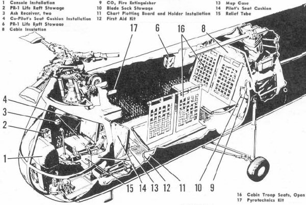

The rescue hoist was mounted above the right front seat and the rescue hatch below it so it had to be removed or folded forward for hoist operations:
Note that the flight controls including the cyclic, as shown above, might remain in place but the seat could not be folded forward unless it was removed.


 However, the pilot and crewman had to be insure that the rescuee didn't grab the controls as he came into the cabin.

There were several instrument panel arrangements. The top one was BuNo 128503-128600.


The cabin interior ended at the attachment point for the aft main landing gear strut;

The engine was mounted aft of the hole in the bottom of the fuselage and backwards, so the drive shaft pointed aft and the engine exhaust stack was forward of the engine.

The engine was mounted at an angle and drove a gearbox that had outputs forward to the front rotor and upwards to the aft rotor.
The engine was encased in a shroud. There was a fan on the "front" of the engine that sucked air in from the openings in the front of the pylon for engine cooling. The air exhausted out the opening in the bottom of the fuselage. An oil cooler was mounted at the rear of the opening.

The above inboard profile was created before the second pair of air inlets was added to the leading edge of the pylon and it appears to have an early version of the trailing edge of the fin. (The second pair of air inlets was added to leading edge of the HUP's aft pylon after it first entered service in order to increase cooling air to its hard working radial engine mounted in the fuselage.) The opening looks like a rounded rectangle from the side but because of the airfoil shape of the pylon cross section and the pylon's interface with the fuselage, it looks very different when viewed from other angles.
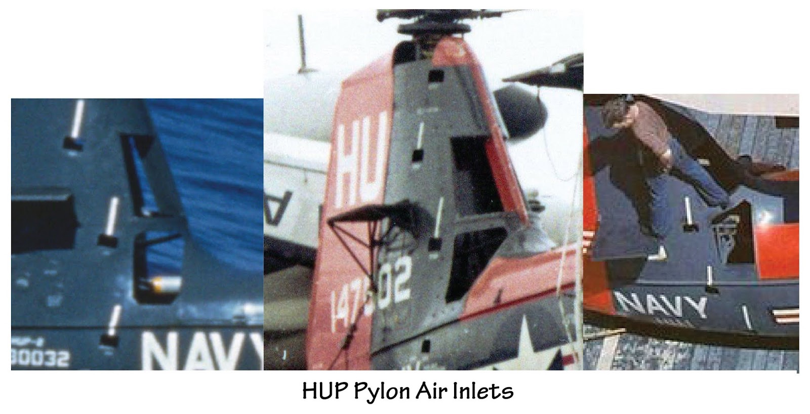
As a result, some kits have gotten the shape of the opening wrong.

This fuselage stations drawing can't be strictly relied on for shape but the station dimensions should be accurate (the overall length of the "shadow" on the ground was 31' 11"):

 Or a bit less as shown on this three view;
Note the shape of the rotor blade on the three view above. There were three different rotor blades. The first type had a tapered rounded tip as shown on the three view. The second had a constant chord of 1' and the outboard section was slightly twisted leading edge down with no taper. The third may be the same the same as the second in overall shape but was all-metal rather than being a wood-covered steel tube.
As far as I know, the rotor diameter was 35' for all blades.

The HUP-3s were H-25s built under contract to the Army. Fifty were delivered to the Navy instead. The H-25s had a slightly different interior and a different rotor head; the Navy may have installed the HUP rotor heads at some point.
(My guess is that the difference was the need for droop stops to keep the rotor from flapping excessively during startups and shutdowns on an aircraft carrier making a relatively high wind over deck for airplane takeoffs and landings.)

Another difference was that some H-25s (51-16577 and 51-16584 and subsequent) had a fairing on the right side of the fuselage associated with the field litter installation ( seen here under the side number of HUP-3 BuNo 147602):
 

For an excellent in-box review of the Amodel 1/72 HUP kit, see http://alexsmodelling.blogspot.ru/2017/03/hup-retriever-amodel-kit-review.html

Gordon Hewstone built the Siga 1/72 UH-25B kit: "It's a relatively crude kit to which I added a few details such as the lights and wiring on the landing gear".

Paul Boyer built the Amodel kit: 


 "The kit is the disappointing AModel kit, probably repackaged from other manufacturers. I also had a Pavla vacuum-formed front “canopy”, but otherwise I used what was in the kit. The rotor heads are over-complicated and under detailed for the scale. I added counterweights at the top and that helps.

The paint is Mr. Color fluorescent red and engine gray. I’ve been holding onto some ALPS decals I think Norm Filer made for me probably 30 years ago! The white “ink” is pretty translucent, so I applied one over another over another - three layers - to look opaque on the Dayglo."

Monday, February 15, 2016

Early P2Vs

Some odds and ends on the differences between the P2V-3 and the P2V-7...

P2V-3 Gun Nose:

P2V-3 Gun Nose vs. P2V-7 forward fuselage:

P2V-3C forward fuselage (significant differences in red) versus P2V-7 (the P2V-7 nose looks a bit off):
Note that for the P2V-7, the bomb bay was bulged downward (a change introduced with the -5), the nose landing gear moved forward to accommodate a bigger radar on the belly, and the canopy raised and relocated forward.
P2V-7 Nose Turret

The P2V-5 nose turret may be similar but the -5 did not have the raised canopy or the forward nose wheel well. (The forward end of the -5 wheel well was at Sta 114, 25" aft of the -7's.)

P2V Tail Turret

Note the rotation of the unit that was introduced at some point early on as a 2° downward rotation of the aft fuselage beginning about half way between the leading edge of the vertical fin and the leading edge of the horizontal stabilizer (it also resulted in the tilting aft of the vertical fin).


Tuesday, November 24, 2015

What's Under the AD Skyraider Canopy?

I have wondered exactly what was behind the headrest of the AD Skyraider canopy. It looked like a tan canvas-like cover that angled down from the top of the headrest to the top of the fuselage just before the aft end of the canopy. And that's just what it appears to be.

The deck behind the headrest is actually the top of the fuselage. The canopy slides on three rails, one on each side of the cockpit and one on the top of the fuselage.

The sliding canopy was powered.
That mechanism appears to be the only hardware under the sliding canopy. Note the "boot" that enclosed the mechanism. It appears to have a closure at the top over the air-to-oil transfer cylinder.

Early Skyraiders did not have the boot.

It appears that it was added to ensure that a leak from the mechanism would not be sprayed into the cockpit enclosure. The boot was not always in place.
The armor plate and seat arrangement (note that the canopy actuation mechanism is not shown).

The headrest that was attached to the armor plate could be tilted forward. Some other pictures;


Saturday, November 7, 2015

KittyHawk XF5U

Kitty Hawk has just released an unusual choice for a plastic model kit, the Vought XF5U-1, in 1/48 scale.

The prototype never actually flew, having been overtaken by jets while it was being designed and built. For a brief history on the program, see http://thanlont.blogspot.com/2012/07/missed-it-by-that-much.html

Here are a few notes on the configuration of the prototype that might be of interest in building the kit.

There are pictures of the prototype before markings were added to the vertical fin.


Some of the few pictures that exist are in a ground-run configuration. Although self-boarding steps were provided, a set of wooden steps were used for ease of accessibility to the cockpit and maintenance-access panels.
A closeup of the temporary and self-boarding steps.

These self-boarding steps are accurately represented on the kit parts based on this built model.
Note, however, that the direction of rotation of the propellers is incorrect on this model.

Handrails were provided for ground run.

The model pictured above doesn't show the prominent cowl flaps and the second set of flaps behind them but the actual kit appears to provide at least separate cowl flaps. (Note that the left-hand flap behind the cowl flap is missing in the following picture.)

This wind-tunnel model included both sets of flaps.

The cowl flaps were repeated on the bottom of the fuselage along with a third cooler outlet flap under the center of the "fuselage".

The tip of the nose was clear because it was intended that a gun camera and approach light be located there.
This drive-train illustration provides an indication as to the location of the coolers:

The tailhook mechanism depicted on the built model looks a little off to me. Here is a annotated diagram from the Vought maintenance instructions.


Note that the tailhook was not installed on the prototype.
Note the location of the steps and the position of the cooling flaps.

A closeup of the pitch and roll control surface (the flaps in the afterbody were for trim).

The best single reference for the XF5U is, as usual, from Steve Ginter.
It can be ordered directly from him: http://www.ginterbooks.com/NAVAL/NF21.htm

Thursday, July 23, 2015

Douglas AD (A-1) Skyraider Pylons

The configuration and orientation of Skyraider weapons pylons comes up from time to time. They are usually not depicted correctly in model kits. This is a work in progress.

The pylon on the inboard wing was perpendicular, i.e. hanging straight down (except on the unique pylon for the big podded radar: see http://tailhooktopics.blogspot.com/2012/11/ad-4n-aps-31-radar-pod.html). The pylons on the outboard wing panel were perpendicular to the wing instead; they were also not evenly spaced.
The view from the side showing the longitudinal spacing of the outboard pylons.

As shown here, the outboard wing pylons were not "swept" at the same angle as the leading edge, i.e. the most outboard one was closer to the wing leading edge than the most inboard.

The external center-line pylon was introduced with the AD-4B and carried forward to the AD-5/6/7:

Note the interface with the oil cooler outlet: the forward end of the pylon is much deeper because it sweeps up into the duct (don't be mislead by the shadow).
 I'm told that the Trumpeter 1/32 center pylon does not angle upward from front to rear as it should.

Early ADs had much smaller and less capable AERO pylons on the outboard wing panel. See http://tailhooktopics.blogspot.com/2013/12/things-under-wings-aero-pylons.html

AD-1s through -4s had a smaller inboard wing pylon than the 5/6/7. The later, longer pylon introduced on the -5 was reportedly necessary to move certain stores farther forward for ground clearance. It also added provisions for the 30-inch lug spacing required for some stores. In addition, it may have been desirable to move the loaded center of gravity forward, particularly on the -5.
Thanks to Ed Barthelmes for a pretty good drawing of the early pylon. However, it has been hard to pin down the exact location of the early pylon on the wing from available drawings. The above drawing is my best guess at the moment.

Here is a direct comparison of the World War II era 1,000 and 2,000 lb bombs on the earlier pylon (note that the 2,000-lb bomb had 30-in lugs and therefore had to be attached with an adapter).
As noted above, ADs before the -4B/5/6/7 did not have an external center pylon. The shackle was mounted within the fuselage along with provisions for an explosive-cartridge actuated "foot" that propelled the bomb downward away from the airplane when dive bombing so that it would not hit the propeller.
 
Illustration from Ed Barthelmes

As a result, the bomb or torpedo was snugged up directly beneath the fuselage.
U.S. Navy via Steve Ginter

Wednesday, July 15, 2015

F6F-5K Drone Strike, Korea

For background on this and the F6F drone program in general, see http://tailspintopics.blogspot.com/2009/11/f6f-drones.html.


Note that the bomb has not tail fins (it's not going to be dropped), the F6F does not have the F6F-5K tailwheel extension (it's not coming back), and the additional antennas for remote control and television picture transmission.

Saturday, May 16, 2015

Special Hobby AF Question

A question was raised about the length of the cowling based on a photograph of a Grumman AF model built from the recently released Special Hobby 1/48th kit, specifically whether it looked a little short. (http://www.britmodeller.com/forums/index.php?/topic/234981898-new-148-grumman-guardian-by-special-hobby/)

Based on a pretty good Grumman three-view, which compared quite well to the Grumman fuselage station data, I calculated that the distance between the leading edge of the wing at the fuselage and the forward edge of the cowling at the fuselage reference line (where the propeller shaft extends), should be 69 mm or about 2 3/4 inches. The kit dimension was subsequently reported to be 65-66 mm.

At that point, I double checked my scaling of the fuselage station drawing (good only for length, not shape, particularly the vertical fin in this instance) and the Grumman three-view and added the AF Standard Aircraft Characteristics side view for comparison. All the drawings compared well in length, with the clear exception being that the wing on the SAC side view was about 3 mm farther forward than on the other two drawings.


I cropped the above to illustrate the difference between the SAC wing location and that of the other two drawings.
It's possible that Special Hobby relied on the SAC sideview for the wing location.

The perceived discrepancy in the picture of the model is likely exaggerated by the camera.