Sunday, June 6, 2021

Grumman F9F-8P Photoflash Cartridge Ejector Pylon

ReccePhreak asked about the F9F-8P's photoflash pod needed for night aerial photography. The answer turned out to be hidden in plain sight and it wasn't a pod but more of a pylon. It isn't identified on the F9F-8P SAC three-view but it's there at Wing Station 96, 25 inches outboard of the pylon used for external tanks and just outboard of the wing fence:

I also found two pictures of it on the wing in Steve Ginter's Naval Fighters Number Sixty-Seven, Grumman F9F-6P/8P Photo-Cougar:

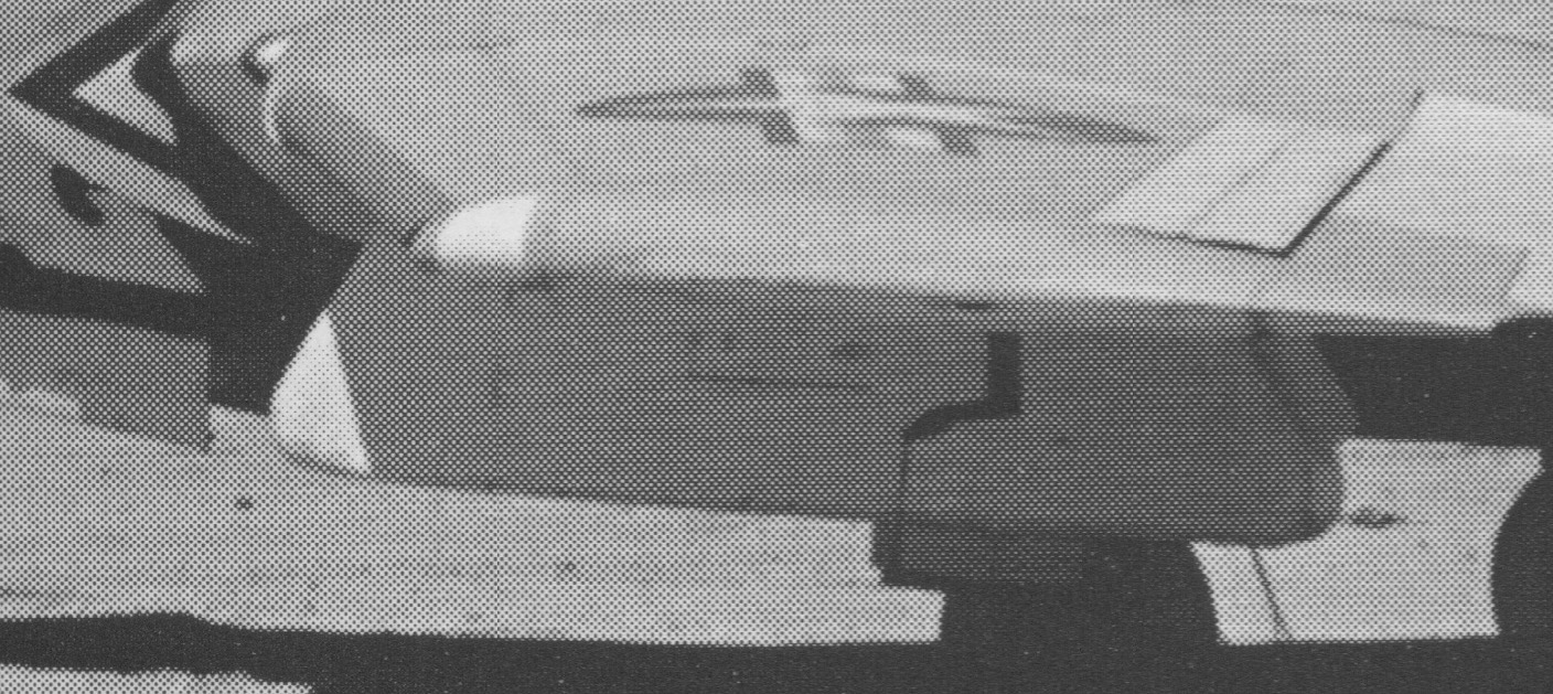
 

And another, not mounted, in my files:

Note that it's about twice the width and depth of the inboard pylon. Jerry Wells then provided me with technical manual information for the F9F-8P and F2H-2P that included a description of the two different flash-cartridge holders and this isometric cutaway illustration of the F9F-8P Mk 51 Mod 14 pylon.

That allowed me to create this notional drawing of the pylon (Butt Line is the same as Wing Station):

Note that the Ejector Type A-6 contains 52 flash cartridges and the B-4, 20 somewhat larger ones.

The F2H-2P did utilize a pod that incorporated the A-6 and B-4 cartridge holders for night photography.


This is my notional illustration of that pod.

One point of confusion is that the F2H technical manual was explicit about a pod with the B-4 ejector being loaded on station 7 only but the 20-cartridge pod in the picture above my drawing is mounted on Station 2 (the eight pylons are numbered from left to right).

Note that the pod in both pictures appears to be mounted on the outboard F2H pylon (station 1/8) that was located farther forward than the next one inboard but that's because a fairing was added on the front of the AERO 14 pylon at station 2/7 to cover the wiring added to control the flash cartridge deployment.

For more on the F2H pylon installation, see http://tailspintopics.blogspot.com/2021/06/mcdonnell-f2h-banshee-stores-pylons.html


Wednesday, February 24, 2021

Westinghouse J40 Afterburner Nozzle

 Afterburning requires a variable exit nozzle that increases the size of the opening for the increased thrust. The nozzle was often fully open during engine start to reduce back pressure and also at idle, to reduce idle thrust.

Afrerburner nozzles now are generally fully variable (or can at least be partially opened in one or more positions) but back in the day in part due to fuel control limitations, were either fully open or fully closed.

Hence the acceptability of a clam-shell nozzle, which is what Westinghouse utilized on the J40:

This is a picture of the rear end of a J40 with the outer shell around the clam-shell halves cut away from 9 to 12 o'clock like the rest of the afterburner section:

Note that the nozzle is fully opened and located between an outer shell and the tailpipe. Also note the flame-holder rings that fed fuel into the afterburner. I'm sure that the interior of the afterburner was not red; it was just painted red on this display engine to differentiate it from the other engine sections.

I don't have a good picture that shows the gap between the two halves of the clam-shell nozzle when it is fully open but this should give you the idea:

The actuator housing was the reason for that small fairing on the side of the fuselage. The natural metal surface is fuselage skin. Aft of that is the dark outer shell of the engine itself and aft of that are the open clam-shell halves.


Wednesday, October 28, 2020

Sword Models 1/72 Turret-less TBM Variants

6 November 2020: Norm Filer provided the following picture and notes on the TBM-3R that he built from the Sword kit described below:

"No significant issues. The usual vague instructions and soft plastic which leads to large sprue gates and sometimes not square mating surfaces. When it is done it looks good."

Original Post:

Sword Models has just released 1/72 scale model kits of airplanes that are not sexy but were ground-breaking in their time, in this case examples of the repurposing the WW II General Motors TBM Avenger, which had been designed, developed, and initially produced by Grumman as the TBF. Attacking capital ships with torpedoes had gone out of fashion by the end of the war, but the TBM was big and sturdy and there were a lot of them left over. As a result, they were quickly and easily adapted to other missions now needing a suitable carrier-based airplane to accomplish. For more on the U.S. Navy TBMs, see http://thanlont.blogspot.com/2015/07/post-war-eastern-tbm-variants.html

All three kits contain the same plastic, including the canopies for each kit. Only the instructions and decals are different.

The first picture is the beautiful art on the cover of the box; the second are profiles of the markings in the kit. 

SW72130 TBM-3SAvenger AS.3/4/6

Unfortunately, the identification of the kit contents is somewhat inaccurate in some places. Instructions and decals are provided for an AS.3 operated by the Royal Canadian Navy (not a TBM-3S, per se) and an ECM.6 operated by the Royal Navy. The AS.4 retained its turret, which is not provided in the kit; I'm not sure that there actually was an AS.6. Only a few (eight?) Royal Navy versions was converted to the ECM.6.

SW72131 TBM-3S2 Avenger

You'll note that the RCN AS.3 depicted here has a slightly different canopy than the one in SW72130 and there are two variations of the -3S2 canopy. The TBM-3S2 was preceded by the very similar TBM-3S (consistent with U.S. Navy designation practice, there was no TBM-3S1), about which more later.

SW72132 TBM-3R Avenger

My personal favorite, the first of the really capable CODs. For more on this variant, see http://tailhooktopics.blogspot.com/2013/01/tbm-3r-cod.html

Note that Sword also plans to issue yet another variant later this year, the very colorful TBM-3U. For more on this particular TBM, see https://tailspintopics.blogspot.com/2020/08/the-colorul-tbm-3u.html

I have yet to do more than fondle the plastic (and haven't seen any online reviews so far) but my first impression is that these kits are highly detailed and excellent quality. The builder will need to pay close attention to the pictorial instuctions because all of the parts, including canopies, for each variant are in each kit. There will be a few parts left over.

Another configuration detail that differentiates the various TBMs is the presence or absence of the external tailhook, which is dependent on which particular TBM-3 or -3E Bureau Number was the basis for the conversion. This is described in the first link above.

More later...


Saturday, September 26, 2020

Grumman F7F-3P Tigercat

The Navy adapted most of its fighters for the photographic-reconnaissance mission. The big Grumman F7F Tigercat was no exception and it was probably the most capable of the propeller-pulled ones. Its five-camera capability included tri-metrogon coverage, which was basically three cameras providing horizon to horizon photographs that could be merged into one. The most forward camera station was for detailed vertical pictures; the pilot was provided with a periscope to aim it. The fifth camera took "flat" oblique pictures to the left side of the airplane.

The aft cockpit was usually occupied by the removable reserve tank since there was nothing for a second crewman to do and the belly tank would block the periscope view. A metal panel often replaced the aft cockpit's plexiglass canopy.

The periscope hatch in the belly just aft of the cockpit was provided with louvers that the pilot opened when taking vertical pictures, pictured here from the left side of the fuselage.

The pilot viewed the image in a mirror located on the floor just left of center.

The big funnel is the viewing end of the periscope (the small black one on the right at the end of a long tube is the pilot's relief tube). The mirror would be mounted in the square plate just in front of it.

When not in use, the open camera ports were covered by metal plates slid into and out of place by cables pulled by electric motors.

The bottom ports and access hatches, looking aft from the right side:

The right-side port (the cover isn't fully closed):

The left-side ports:


The four cannons located in the wing leading edge between the fuselage and engines were removed. However, it appears that there were at least provisions for the .50-caliber machine guns mounted in the nose since the gun ports are present.

For a summary of the various Tigercat versions, see https://tailhooktopics.blogspot.com/2016/11/grumman-f7f-tigercat-variations.html


Sunday, June 14, 2020

A-3 Versions Windows

A question has arisen with respect to the number of windows on the side of the fuselage of the A-3 mission variants. The variants were derivatives of the A3D-2 bomber that had the bomb bay deleted and the forward fuel cell moved aft to create a cabin just aft of the flight deck. For more, see https://tailspintopics.blogspot.com/2010/09/mighty-skywarrior.html

The variants were the A3D-2P (RA-3B), A3D-2Q (EA-3B), and A3D-2T (TA-3B). Some A3D-2Ts (and reportedly an EA-3B) were outfitted as a transport and at least one was converted to an EA-3B. Subsequent repurposing of the RA-3B resulted in the ERA-3B.

The A3D-2P was easily recognizable for its camera port fairings and the single porthole on the side of the fuselage. The A3D-2Q had three windows and a door on the right side of the fuselage; there were no windows on the left side of the fuselage as the left side of the cabin was filled with consoles. The A3D-2T had four windows on the left side in addition to the windows and door on the right side.

As it happens, all of the variants were built with provisions for all the windows on both sides of the fuselage with the exception of the A3D-2P. It is likely that on them at least the third window going aft on the left side and the door on the right side were deleted during the redesign to reconfigure the aft end of the cabin as a small bomb bay. It's possible that provision for the aft window opening on each side of the fuselage was also deleted but an early Douglas access-panel drawing has it present.

Some have questioned why the versions were all built with the window provisions, some of which were then plugged. The answer is that metal airplane structure is made up of bits and pieces. Every one is created using patterns/dies (aka tools) to cut it to size, bend it to shape, drill holes in it, inspect it, etc. More tools (aka jigs) are used to combine parts into assemblies and so on. As a result, if the weight penalty is small enough, in order to minimize nonrecurring cost and to some extent take advantage of the learning curve and minimize investment in spare and repair parts inventory, etc, when an assembly is to be used for multiple applications, the lowest common denominator configuration is designed and then modified as required. There were other production control benefits as well,

Others have questioned that there were provisions for windows when none are apparent in photos of the airplane. The answer is that putty and primer obscure the presence of the frames and inserts, particularly if the pictures are not very high in resolution.

This is a picture of the left side of an EA-3B undergoing a major overhaul, stripped down to bare metal.
 Angelo Romano

This is a picture of the right side of the fuselage of an ERA-3B. The outline of the window frame aft of the porthole is faint but definitely present on the original scan.
Rick Morgan

However, for any model in a scale less than full size (if then), the time to depict the presence of these frames could probably be best spent elsewhere.


Friday, April 17, 2020

Lockheed P2V Neptune Crew Entry Hatch

 21 April 2020: In turns out, thanks to photos and illustrations provided by Ed Barthelmes that the P2V-5 (and presumably earlier and maybe the P2V-6) and the P2V-7 had slightly different entry hatches. The photos I took and originally posted were of the nose wheel well of a P2V-5FS.

For more on the P2V-5 versus the -7, see http://tailspintopics.blogspot.com/2020/03/lockheed-p2v-5-vs-7-neptune.html

All P2Vs had a crawl way to the left side of the nose-gear wheel well (which is why the well is offset to the right) and beneath the flight deck for access to the aircraft and to go between the nose and the forward crew compartment. This is a P2V-5 illustration:
 
Access to the crawl way from the ground was through the aft left side of the nose wheel well (note that the above illustrates the access point for P2Vs -1 through -6; because the nose wheel well was located farther forward on the P2V-7, the opening was located farther forward in the crawl way).

This is from the P2V-5 manual; note the width of the wheel well relative to the ladder:

The access could be closed off by sliding panels, in this case a picture of the P2V-5's.

Note the folding ladder attached to the aft end of the wheel well, again on a P2V-5.

Note that the earlier P2Vs had a wider nose-wheel well than the -7.

This is a picture of the hatch in a P2V-7; note that it slides open vertically and appears to be wider than the -5's.

 Ed Barthelmes

 This one shows the ladder (and the sole of somebody's shoe):
Ed Barthelmes
This is the open hatch in the wheel well of a P2V-1 (it isn't evident what closed it off; I suspect that the ladder was removed to discourage entry to the airplane after it became a museum display):

 This is the location of the opening in the floor of the forward crew compartment.
 Ed Barthelmes

There was another hatch on the bottom of the fuselage aft of the bomb bay for entry to the fuselage aft of the wing (it was possible to go between the forward and aft crew compartment but it required crawling over the wing spar) as shown in this P2V-5 illustration provided by Ed Barthelmes.
