Monday, September 16, 2019

Sikorsky ASW HO3S-3

Sikorsky's S-55 design rectified an increasingly significant shortcoming of his helicopters up to that point, which was the lack of relatively indiscriminate loading of cargo and/or passengers because the single-rotor helicopter could not accommodate a wide center-of-gravity range.  As a result, he lost a Navy competition for a plane-guard helicopter—a mission that he had pioneered, promoted and provided the first helicopters for—to Piasecki, who proposed one with his tandem-rotor configuration that had a wide cg range.

In the S-55, he located the passenger/cargo cabin directly under the rotor and the fuel tanks directly under the cabin, minimizing cg travel due to loading/unloading passengers/cargo and fuel burn. The engine, which had been located directly under the rotor to simplify the drive train, was moved to the  nose. The cockpit, which had been in the nose, was relocated above and forward of the cabin. The Army awarded him a development contract for it on behalf of the U.S. Air Force as the YH-19. First flight was accomplished on 7 November 1949.

A military service has always been quick to adapt a successful helicopter design to its own mission requirements whenever one is generally suitable, since helicopter development generally had and has a low priority relative to other demands for funds. And so it was that the Navy, needing an ASW dipping-sonar test and evaluation helicopter until Bell's HSL ASW helicopter (see http://tommythomason.com/books/Bell-HSL/) completed development, procured the S-55 as its HO4S-1 in April 1950. The 600 hp takeoff rating of the -1's P&W R-1340 proved inadequate for the hover performance required for the dipping-sonar mission so it was replaced for HO4S-3 production with the Wright R-1300 with an 800 hp takeoff rating, although at least initially it was limited to 700 hp by the helicopter's drive system.

As a result of the delays in the development of the Bell HSL that was intended to be the Navy's operational ASW dipping-sonar helicopter, the Navy procured the HO4S-3 as a placeholder until either the Bell HSL or the backup program it had initiated with Sikosky for the HSS (now better known as the H-34) could be deployed.

The multi-tank fuel system in the belly of the fuselage allowed for an opening in the bottom of the fuselage for deployment of the sonar.

Note the large oval-shaped fairing on the belly around the opening. My guess is that this covered up the fuel lines that interconnected the tanks and I would appreciate receiving a more informed explanation.

The bottom of the sonar dome could extend beyond the bottom of the fuselage when not fully retracted. (Note that this HO3S does not have a rescue hoist.)

The configuration of the sonar dome changed over time the one utilized by the HO3S looked like this.

The "ball" was flat on one side, with the antenna surface protected by a wire screen.

The cable reel was housed in the cabin. The enclosure design also changed over time so this may just be representative.

The sonar operator's station looked something like this (there may have been a second seat beside it in some cases):

He could control the depth of the sonar and determine the distance and relative bearing of a contact.

The HO3S-3 could be armed with a single Mk 43 homing torpedo that was mounted on and dropped from a variable-angle rack on the left hand side of the fuselage.


This is the best picture I have of the rack:

This is the HSS rack, which appears to be very similar (note that the forward sway brace has been "cut off" by the draftsman so as not to hide details behind it).
The "lever" extending aft of the rack pulled out the pin from the torpedo that armed it and/or started its turbine.

The addition of the 375-lb torpedo generally limited the operational use of the HO3S to hunter-killer tactics, with the three-man crew of the hunter (pilot, copilot, and sonar operator) reduced to two (pilot and "bombardier") when the torpedo was carried.

Note that the Air Force and Army H-19s were subsequently modified with a different tail boom, bigger vertical fin, and much smaller horizontal stabilizer with no anhedral.
Angling the tail boom down reduced the propensity of main rotor blade strikes on it. As far as I know, no Navy or Marine S-55s received this mod.

Information on and illustrations of the Royal Canadian Navy HO3S-3 can be found here: http://jproc.ca/rrp/rrp3/ho4s3.html

Monday, September 9, 2019

Grumman F6F Hellcat Belly Tank

Another interesting question - what are the different F6F 150-gallon belly tanks?

I don't have a complete answer but I do have some information. First, the F6F belly tank had to be nonstandard because of the location of the oil cooler air outlet.


It was located pretty close to the desired center of gravity, which is where you want the disposable load to be if at all possible so the cg doesn't change much when you use fuel, drop bombs, etc.

When the Navy decided the F6F needed more fuel, Grumman developed an attachment approach evaluated on an early F6F (note the wheel covers) that provided clearance with the oil cooler air outlet.

It was refined to this (note that it has the later rectangular pylon):
The two retaining straps kept the tank from falling off and allowed it to be jettisoned (note the two holes on either side of the oil cooler air outlet above that allow them to be attached to standard bomb shackles). The pylon on the aft end of the tank contained the plumbing that transferred the fuel in the tank to the airplane's fuel system and along with the two sway braces, provided the separation between the tank and the bottom of the fuselage.

The leading and trailing edges of the early production pylon was curved instead of straight as on the subsequent one.
Note the rectangular profile of the later pylon fairing on 69Z versus the early streamlined one on 68Z. The latter is white to match the bottom color of the early F6F camouflage. The tanks were obviously interchangeable.

The early tank appears to have invariably had a vertical flange, separating the left and right halves of the tank.

The later tank had a vertical flange initially as shown in the illustration above and then was subsequently produced with a horizontal flange.

The tank was also changed from aluminum to steel at some point, possibly in conjunction with the change in the pylon fairing shape, because of the relative availability of steel versus aluminum.

In April 1945, a Service Change was issued to enable the F6F to carry the new "universal" 150-gallon tank. The retaining straps were basically the same, the forward sway braces were interconnected, a fuselage mounted strut was added to hold the aft part of the tank away from the fuselage, and a flexible hose was added to transfer the fuel from the tank to the original fitting on the bottom of the fuselage.

Thursday, September 5, 2019

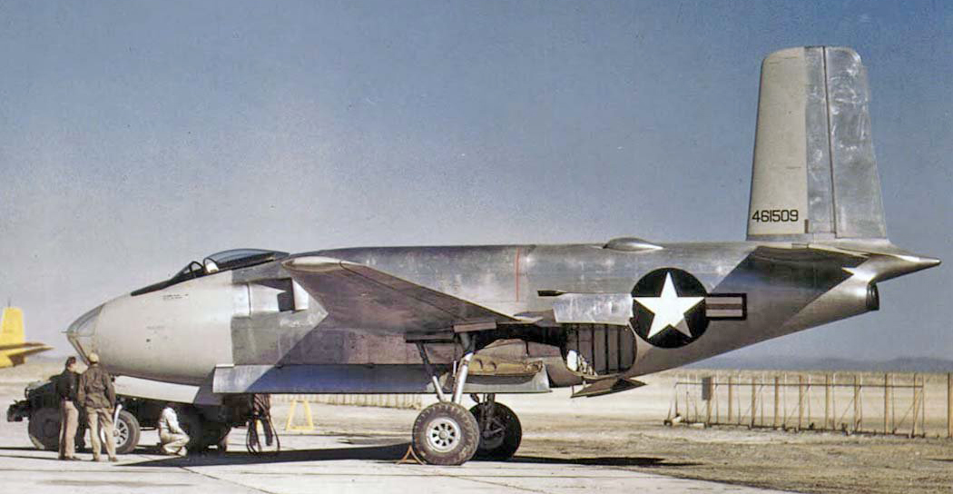
Douglas XB-42/43 Main Landing Gear


Sometimes the question is so interesting that I can't stop myself from trying to answer it. In this case it was the configuration and operation of the Douglas XB-42/43 main landing gear. For background on the program, see https://oldmachinepress.com/2017/08/05/douglas-xb-42-mixmaster-attack-bomber/

The interesting question was how the fuselage-mounted landing gear went from being extended with the wheel outboard of the strut (see picture above) to retracted with the wheel inboard of the strut, which was covered by a bulge along the underside of the wing when retracted. My guess is that the retracted arrangement was desired to minimize the internal space required for a wheel well. Note that this picture is of the propeller-driven XB-42, which had a slightly different gear door arrangement than the jet-propelled XB-43's.

I mocked up the strut and wheel using a rotating-head toothbrush, a paper clip, and a toothpick for the angle of rotation.
The answer was that it could be done with a single axis of rotation, angled at about 45 degrees to the strut (the axis of rotation might also be angled a bit laterally but determining that exactly would have been a even bigger time-waster).

The landing gear door arrangement was about as convoluted as I have ever seen, even after it was probably simplified for the B-43.
When retracted, the wheel is covered by three separate doors, the middle one being hinged to the upper one rather than the fuselage. The bigger door that covers the strut drops well down on large goose-neck hinges to be out of the way when the gear is retracting. Then there is a small door under the wing that appears to allow the forward side of the upper end of the strut to swing aft and a larger one forward that covers the drag link/retraction actuator after gear retraction.

Ian Shillingford created a 3D video model of the retraction:


One thing he noticed was the vertical fork on the strut: "it is now
obvious that that fork attaches to the rear wing spar when the
undercarriage is extended to transfer the weight away from the strut
hinge and onto the spar".


Friday, August 2, 2019

F4H (F-4) Phantom Main Landing Gear Shrink Mechanism

Airplane designers sometimes want to make the landing gear shorter when it is retracted, i.e. compress the shock strut from its extended position when it is in the air, for various reasons. Here are a couple of examples of nose gears that "shrink":

http://tailhooktopics.blogspot.com/2019/07/mcdonnell-f2h-banshee-nose-landing-gear.html

https://tailhooktopics.blogspot.com/2019/04/mcdonnell-f3h-demon-nose-landing-gear.html

The main landing gear on the F4H Phantom is another example but one that is even less obvious. Note that the tricky part of providing a shrink capability is that the lower portion of the strut must be allowed to extend and compress freely when the gear is extended.

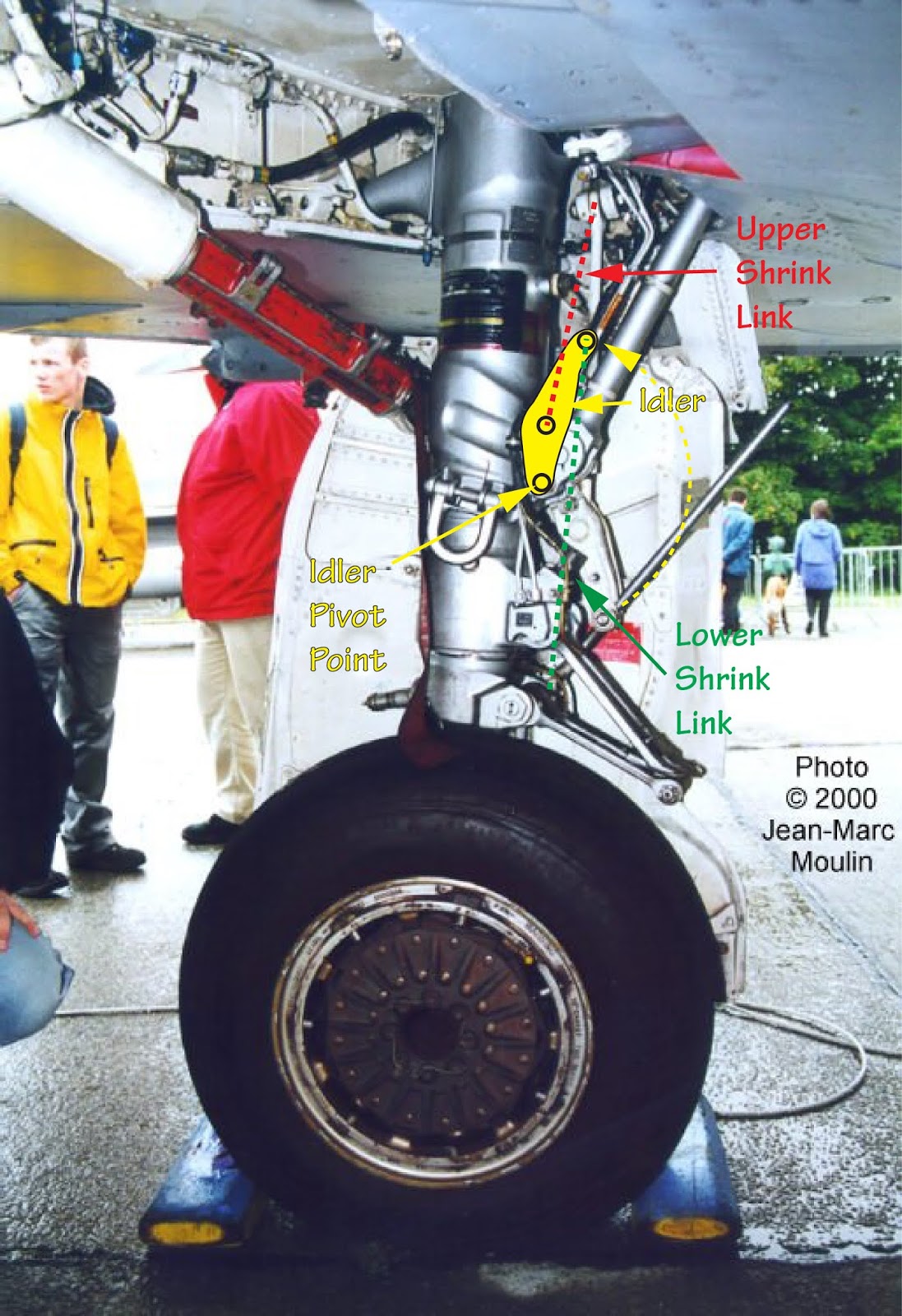
This Jean-Marc Moulin picture shows the basic elements of the F4H main landing gear shrink mechanism.


Note that there are three components to the mechanism: the upper shrink link, the lower shrink link, and the idler that connects them, all located on the rear outboard side of the main landing gear shock strut.  The lower shrink link is attached to the lower part of the shock strut and can slide freely through the idler until the link reaches a stop on its upper end (the scissors or some other feature within the strut probably establishes the length of lower strut travel but the stop is necessary for the shrink function). That allows the shock strut to extend about 17-18 inches when the wheel is not on the ground. Also note the location of the pivot point of the upper shrink link, which is outboard of the pivot point of the main landing gear strut itself.

When the landing gear is retracted, these three components, combined with the location of the upper shrink link pivot point, cause the shock strut to compress significantly.

Because the upper shrink link pivot point is outboard of the strut's pivot point, it is in effect shortened that many inches relative to the shock strut when the landing gear is retracted. That pulls the idler up against the strut, which causes the lower shrink link to pull the lower part of the shock strut on which the wheel is mounted back up into the upper part.

This Howard Mason picture shows the components of the mechanism on the left main gear from the rear.

 Howard Mason

Tuesday, July 23, 2019

McDonnell F2H Banshee Nose Landing Gear

McDonnell redesigned the nose landing gear of the F2H-1/2 Banshee for the heavier F2H-3/4 so that the strut could be extended for a catapult launch at a higher initial angle of attack.

The -1/2 nose gear was a trailing-arm configuration with no separate scissors to keep the upper and lower sections of the shock strut aligned. The -3/4 had a separate scissors with the nose gear fork swiveling on a bearing mounted on the front of the shock strut.
The nose wheels were the same diameter. The redesign resulted in it being located farther forward relative to the nose wheel well.
Note that the nose wheel axle is located directly under the shock strut on the -3/4 Banshee rather than significantly behind it as on the -1/2 and the nose landing gear doors are splayed out on the -1/2 and vertical on the -3/4.

The shimmy damper was relocated to the lower side of the shock strut and a shrink strut was added to compress the shock strut as the landing gear retracted.

Most of this detail was hidden by the nose gear doors when the airplane was on the ground.

Friday, July 5, 2019

North American FJ-4/4B Main Landing Gear

A question has been asked about the accuracy of the FJ-4 main landing gear in model kits.

The FJ-4 main landing gear was different from the FJ-2 and FJ-3's. It was a so-called trailing arm configuration, which separated the landing gear strut from the shock absorption function. My guess is that this was done in this instance to reduce the width of the landing gear when viewed from the front, because the FJ-4 wing was thinner to increase the airplane's critical Mach number (there are other benefits - see John Eaton's comment below).

This is the best picture I've found so far of the configuration:
Note that the piston of the shock strut extends above it and shock strut is attached to the one-piece trailing arm forward of the wheel's axle. Roughly speaking, a line drawn between the trailing arm pivot point (see below) and the wheel axle should be parallel to the ground.

Static-display FJ-4s may have the shock strut fully collapsed as in this picture:
Photo by Fotios Rouch

What's worse, the display FJ-4B might not have the correct wheel hub:
Bill Spidle Photos

 The actual main landing gear hub/wheel appears to be identical to the F4D's:
https://tailspintopics.blogspot.com/2015/07/its-not-that-easy-to-avoid-error.html


The main landing gear is angled aft, probably because of the desired location for the mounting structure in the wing versus the required location of the wheel relative to the airplane cg. The trailing arm is not accurately depicted - it actually has a kink in it between the gear strut and the wheel as shown above.

Note that the tire diameter is given as 26", which is the green circle.

The kink in the trailing arm is required to allow full extension of the shock absorber.

The main landing gear wheel doesn't appear to have changed during its service life, always being the "forged" configuration. The nose landing gear wheel does seem to be different in some instances.
Note that the "link" extending aft of the shock strut is attached to the swiveling section of the nose landing gear and "rides" a ramp in the wheel well to mechanically rotate the wheel so it lies flat in the wheel well.

Proper "sit" is important to a model's appearance on its landing gear. Note however, that it will vary with the weight of the airplane (with and without full fuel and external stores). If the airplane's brakes are applied while it is being towed or pushed back, the nose gear strut may also compress or extend slightly, changing the true static sit.

Note that I've corrected the original drawing for height vs width using the water lines versus fuselage stations and also sloppy drafting. The dashed line is the location of the ground with respect to the overall heights given above the canopy and the vertical fin. (For 1/48, the box is 9" x 13.5")


Wednesday, May 29, 2019

Grumman F9F-8 Upper Control Surface Color

Every so often, there is a color-scheme or markings query that calls into question how sure one can be about the answer.

Today's example is the color of the upper surface of the flight controls of an F9F-8 Cougar in the Gray/White scheme. At least early on, new production aircraft had gray rudders (the scheme would eventually require white rudders but an F9F-8 with a white rudder is pretty rare). The whole upper surface of the horizontal tail was white, rather than just the elevators. The upper surface of the flaps was white as was the small trimmer on the trailing edge of the left wing near its tip. However, the roll-control spoilers forward of the flaps were initially gray, although the aileron equivalent was usually white like the elevators in order to minimize damage from the thermal effect from the detonation of a near-by nuclear bomb. The roll-control spoilers were subsequently painted white.

Note that the color scheme subsequently approved for use by Navy overhaul and repair facilities might not be exactly the same as the one that Grumman signed up for in a production contract.

And then there's this picture of four F9F-8Bs, circa 1957:


Note that two have white horizontal stabilizers, one has gray, and one is something else (possibly spares that were already painted gloss sea blue). The two with non-white horizontal stabilizers have white spoilers.

As a general rule, however,  F9F-8s in Navy fighter squadrons with a single-letter tail code do not have white spoilers while those with two-letter tail codes do (the change to two-letter codes was decided upon in mid-1956 but was probably not fully complied with for at least a few months). There are exceptions. Also, with the exception of the above picture, I haven't noticed any Navy F9F-8s that have the upper surface of the horizontal stabilizers painted.

Comments, corrections, and additions welcome.