Sunday, January 11, 2026

Piasecki HUP Landing Gear

12 January 2006: Corrected three-view illustration

For more information on the interior and exterior, click here: https://tailhooktopics.blogspot.com/2016/04/piasecki-hup-interior.html 

An aircraft's landing gear is often inaccurately depicted in a model aircraft kit for various reasons, but primarily due to reliance on a museum example that does not have properly inflated struts. Helicopter landing gears are even more likely to be incorrectly represented on a model particularly when they involve multiple small struts for which proper alignment features (or adequate illustration in the assembly instructions for that matter) are provided.

The Piasecki HUP main landing gear is an example. It consists of a main shock strut that is mounted upside down (the piston extends out of the top of the strut) with lateral and longitudinal loads reacted by two small struts attached to the bottom of the fuselage that are joined together at their outboard ends and attached to the bottom of the strut shock with a yoke.

 When the strut is properly serviced, on the ground there will be 2.1 inches of chrome-plated piston above the cylinder and the top of the chrome will be 12.44 inches from the attach point of the strut on the fuselage.

 Note that longer lateral strut is mostly hidden behind the short one from the side:

Also note that when the HUP is off the ground, the wheels drop down about 11 inches (note the additional chrome showing on the piston) to provide the shock absorption of a high sink-rate landing.


Saturday, December 6, 2025

Lockheed T-33 Tip Tank

 12 December 2025: Slightly different overall dimensions have been reported based on measuring tanks or ones on display aircraft, lengths of 182", 182.5", and 186" and diameters (constant section) of 25.5", 25.78" and 25.783", which sounds like a conversion from a metric measurement. The 182.5" is reportedly also taken from a stations diagram, which is close to a gold standards; the 25.5" is based on a careful measurement of the circumference of a tank as 80" (a second tank measured slightly less), which calculates to a diameter of 25.465" using pi to five places. I would note, particularly with respect to the somewhat snarky insistence on 25.783", that any of those diameter measurements will suffice since the difference is minuscule at model scales.

Someone asked for the dimensions of the Fletcher tip tank carried by the T-33 (and occasionally seen on the F-84 Thunderjet), so down another rabbit hole I went. Thanks to Jerry Wells, who measured and photographed the example at the National Naval Aviation Museum in Pensacola, this is the result:

One feature is a removable two-piece fairing that covers up the cavity where the tank is attached to the wing tip:


Ricardo Reis Photo

 Jerry Wells Photo

 
 Jerry Wells Photo

The trailing edge of the fin at the aft end of the tank is angled slightly forward and the tank is mounted with it parallel to the ground, not with dihedral like the wing.


Jerry Wells Photo

 Note the little access door on the inside of the aft end of the left tank only for storage of safety pins, etc.


Jerry Wells Photo


Monday, November 10, 2025

Boeing B-52 Stratofortress Wing Dihedral


And now for something completely different but it's a rabbit hole I've explored fairly thoroughly so I thought I'd share. Thanks to Ron VanDerwarker, Rob de Bie, and Haydn Hughes for information.

The B-52 is rightly famous for the bending of its high-aspect-ratio wing in flight as well as on the ground, the amount varying considerably with aerodynamic and fuel loads.


Note that the airplane is restricted in g loading to lower numbers operationally but during initial development it was taken to at least 3.5 gs.

Some believe based on three-view drawings and pictures of the airplane on the ground that the B-52 wing has anhedral (wing angled down, also known as cathedral) rather than dihedral (wing angled up).

However, the appearance of anhedral when on the ground is deceptive, a combination of a swept wing viewed at an angle of incidence from the front (also see https://tailspintopics.blogspot.com/2014/03/anhedraldihedral-and-wing-sweep.html) exacerbated by the significant droop of the B-52's wing when fully fueled and stationary.  

This B-52D three-view drawing appears to be both Boeing-generated and accurate, although the top view has slightly greater wing span than the front view, not unusual and resulting from differential sizing of the views.
 
Based on this drawing, I’ve verified that the wing has dihedral:


The blue line is the wing's angle of incidence (6°) relative to the fuselage; the red line is along the wing leading edge. The difference between the two indicates dihedral (I don’t know what definition was used for measuring it, but it was possibly the trailing edge).
 
This Boeing illustration also depicts the dihedral present at the wing root with the scan distortion corrected with red lines:
 
Note that the clearance depicted on the Boeing three-view under the engine pods, external tank, and wing tip is dependent on fuel load in the wing and tip tank.
I’m pretty sure that “jigged" means that the three-view drawing does not show wing droop, i.e. the wing is drawn with a dihedral of 2.5°, which is possibly the case when the wing and tip tank are empty of fuel.
 
With no fuel in the wing or the tip tank, the auxiliary landing gear out on the wing tip would be well off the ground with no wing droop.

 
When generating lift, of course, the wing bent upward along its span.
 
For modelers building a B-52, there are two ways of incorporating wing bending if desired: 1) bending the wing and 2) modifying the angle of the attachment of the wing to the fuselage. The latter is incorrect and doesn't accurately represent the bending of the wing itself along its span but is an easier way of positioning the wing tip correctly with respect to the ground for a given fuel load. Nevertheless, Haydn Hughes did the former successfully: "Back in 2002 I made a couple of saw cuts in each wing of slightly different widths and inserted strips of plastic card until I got what I thought was a reasonable 'bend' in the wing. This did mean I had to replace the vortex generators though!"
 
My guess is that it would be more accurate to make the saw cuts perpendicular to the leading edge.
 
Another suggestion for bending the wing is to assemble the wing halves and then make razor cuts in the lower wing (probably best perpendicular to the leading edge and including a bit of the leading and trailing edge of the upper wing) and then gluing the gaps closed. Note that the wing outboard of the external tank will have very little if any droop. 

Monday, March 31, 2025

Ginter Books


 Steve Ginter no longer has his own website but he is still creating and publishing books. You can contact him directly for availability and pricing (nfbooks@sbcglobal.net ) or look for them here: https://daviddoylebooks.com/search?q=Ginter

Sunday, November 17, 2024

USMC F7U-3s

 The Naval Ordnance Laboratory Test Facility at Fort Lauderdale, Florida was assigned responsibility for qualification of airborne delivery of anti-ship mines. They utilized aircraft assigned to NAS Miami for drop testing. In February 1952, the air station was transferred to the Marine Corps, which inherited the test requirement. The qualification of a large, heavy mine intended for 500-kt delivery from 500 feet by the Navy's big new jet-powered patrol plane, the Martin P6M Seamaster, required a much bigger, faster jet than an aircraft in the USMC inventory, so Miami was assigned three F7U-3s over time.

The first, BuNo 128466, was one of the first sixteen F7U-3s that were powered by non-afterburning J-35 engines. It had become excess to Vought and Navy test requirements. It arrived on 30 August 1954.


It's availability proved disappointing due to a lack of spare parts among other things so it was retired in favor of a J46-powered F7U-3, BuNo 129582, which arrived on 21 July 1955..


It was stricken on 1 July 1957, probably in lieu of a required overhaul, and replaced by BuNo 129602 that was fresh out of overhaul (unfortunately, Al Casby has been unable to acquire a picture of this F7U-3 in USMC Miami markings). When no longer required for testing a year later, it was ferried for storage at NAF Litchfield Park.

Early F7U-3 Forward Fuselage

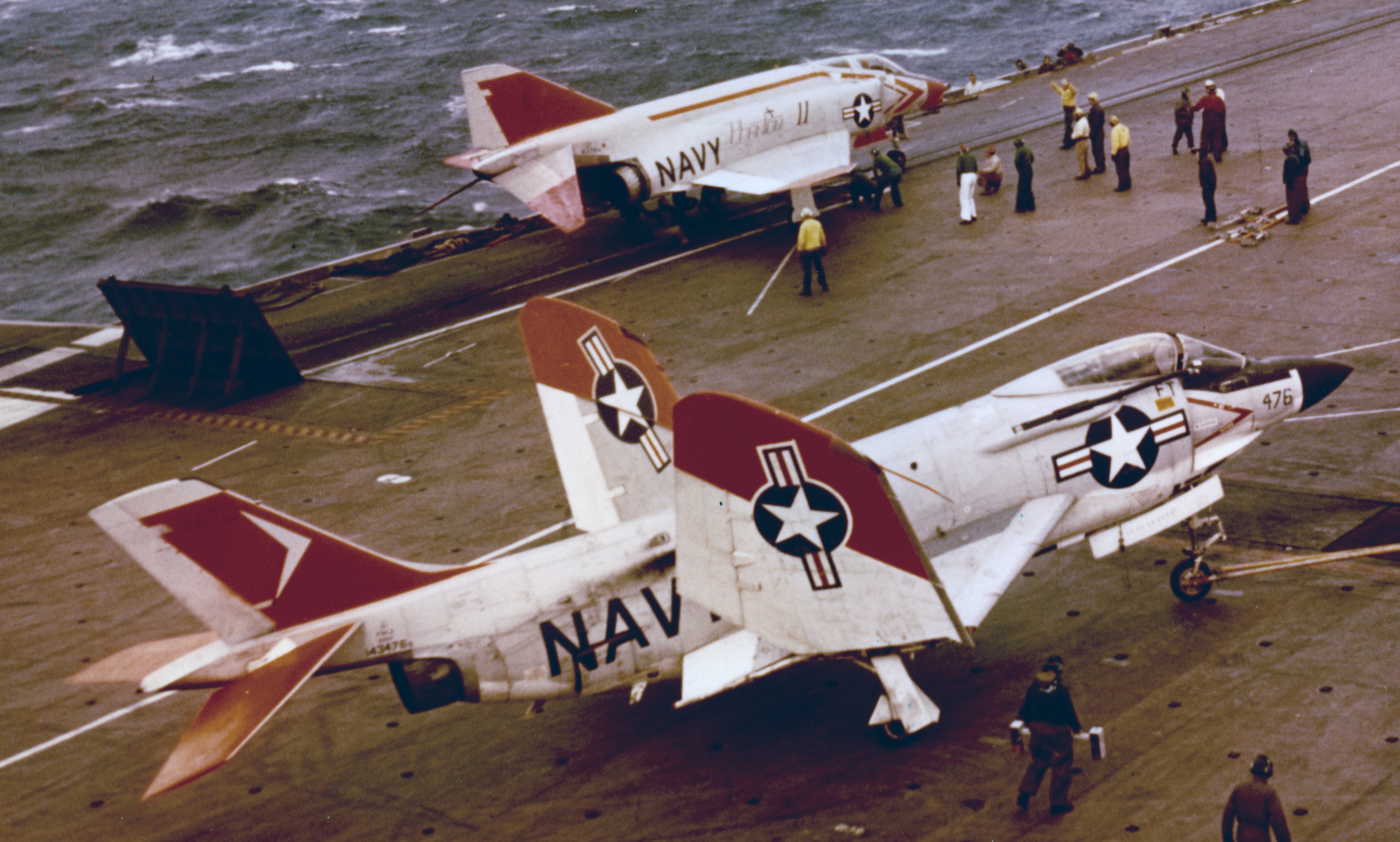
 The first 16 F7U-3s were powered by nonafterburning Allison J35 engines because the Westinghouse afterburning J46 engines were not yet flight qualified. One was modified before first its first flight to have the over-the-nose visibility increased for carrier landings. As a result, the radome, canopy, and engine inlet/tailpipe were very different.


The vertical fin was also modified during development to provide more deck clearance for takeoff and landing:

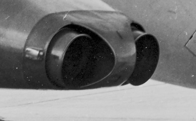
The Allison-powered F7U-3s had different inlets and tail pipes because of the greater mass flow requirement for maximum thrust and the lack of an afterburner.

Inlet without boundary layer splitter:

Simple tailpipe:


Friday, March 8, 2024

FS 12197 International Orange

 FS 12197, International Orange, has been used on U.S. Navy aircraft for high-visibility markings. It can be confused with other colors also used for that purpose. Also note that it is more red-orange than orange...


For example, Robert Thomas, a volunteer at the National Naval Aviation Museum in Pensacola, provided this synopsis:

"For the high visibility markings the USN originally used the Orange Yellow color (think the SNJ, etc.). In the early 1950s they started using International Orange on some aircraft. The Naval Air Training Command in 1952 tested various colors in hopes of better visibility. In September 1952 "Day-Glo" paint had been developed. It was labor intensive, as it had to be applied over a White lacquer finish, needed two coats, and started dulling after one to two months. After trying other paint designs, they went back to the Orange Yellow overall markings. In 1953 the USN discontinued all use of Day-Glo paint.

In 1956 International Orange paint began to be used on tactical aircraft in the continental U.S. due to the increased chance of air-to-air collisions with civilian aircraft. In 1958 Fluorescent Red Orange replaced International Orange as the standard high-visibility paint on non-training aircraft. 
In 1959 the Training Command went completely to an International Orange and White paint scheme.

In May 1964 the Navy discontinued use of fluorescent Red Orange. It also required high upkeep due to fading issues. At that point all high-visibility paint markings were to be in International Orange only, which is still used today on training a/c and where necessary on other types.
The FS numbers appear to not have changed over the years. International Orange is FS12197 and Fluorescent Red Orange is FS28913. Orange Yellow is FS13538."

A color in a published illustration or on a computer screen is not always rendered accurately so even the color above is not necessarily true. It may not even appear to be consistent in the same picture: 

Note that the color on the top of the left wing appears to be more orange than the bottom of the left wing or vertical fin (which both appear to be more red than the sample above) and the horizontal stabilizers appear to be somewhere in between.

Even a direct comparison with insignia red in a pretty good photo isn't necessarily helpful:

 Of course, the underlying prime coat or adjacent color to the International Orange may affect its appearance:


Available 12197 paints also vary in color. Paul Boyer recommends Testor Model Master “Chevy Engine Red” (if you can find it) especially under artificial light; in his opinion, Testor Model Master “International Orange (FS12197)" was too dull in artificial light. Others have found Model Master Acrylic 4682 and XtraColour X104 to be too orange.

Other recommendations found on line:

https://www.cybermodeler.com/color/fs_table.shtml

 https://www.scalemates.com/colors/hataka-hobby-red-line--997/a062-international-orange-fs12197-ana-508-acrylic-gloss--9859

 https://www.truenorthpaints.com/paintstore/international-orange (looks too orange on my screen)

https://www.arizonahobbies.com/US-Air-Force-INTERNATIONAL-ORANGE-FS-12197-2-oz-bottle_p_4600.html (looks good on my screen)

 Rustoleum "Allis Chalmers Orange”

And probably as good as any, "red with some yellow added".


Tuesday, July 4, 2023

Grumman S2F Bomb Bay

 From Grumman Archives:


Friday, June 30, 2023

A-6A versus A-6E Inboard Wing Fence Locations

 1 July 2023: It turns out that there is the same drafting error on two different Grumman drawings with respect to the location of the inboard end of the leading edge slat. I've corrected it.

A question arose about the the location of the inboard end of the wing slat on the A-6A versus the A-6E with the inboard wing leading edge ECM antennas. The answer is that it was not changed. Note however, that the inboard wing fence location did change: it was moved inboard of the inboard pylon.

All dimensions shown are "wing stations" measured from the fuselage centerline.

For more on the major configuration differences between the A-6A and A-6E, click here: https://tailspintopics.blogspot.com/2015/09/grumman-6a-vs-6e-intruder.html


Tuesday, June 27, 2023

McDonnell F2H Banshee Canopy Actuation

The F2H Banshee canopy was actuated by a rack and pinion mechanism. The rack was mounted fore and aft on the canopy, attached at its aft end and underneath the cross brace. The pinion was driven by an electric motor mounted on the deck under the canopy. The rack was angled slightly upward going aft so as the pinion turned, the aft end of the canopy moved upward as well as aft. The forward attach points of the canopy were in a track that caused the front end of the canopy to go up as well as aft also for clearance of the pilot's helmet. The -1/2 and -3/4 canopy actuators are very similar if not identical. 

The F2H-2 canopy:

Closed (early windscreen):

Open:


Friday, March 24, 2023

Douglas A3D-2P/RA-3B Skywarrior Cockpit

 As with most photographic-reconnaissance airplanes, the pilot was provided with a periscope so he could  orient the airplane for pictures taken by his downward-oriented cameras. The A3D-2P had two periscopes, one for the pilot to position the airplane over the area of interest and one for the photo-navigator in the right seat to trigger the cameras to take pictures of it.


 The viewfinders were large and prominent on the instrument panel:

The cylinder below the viewfinder for the photo-navigator was a radar scope.

Sunday, February 19, 2023

Miscellaneous Paint and Markings Notes - U.S. Navy Aircraft

 This is a work in progress and to paraphrase Captain Barbossa, specifications are more what you'd call "guidelines" than actual "rules". For example: https://tailspintopics.blogspot.com/2012/06/markings-cautionary-example.html and https://tailhooktopics.blogspot.com/2019/05/grumman-f9f-8-upper-control-surface.html

Summary, 1940 to Gray/White: 

https://tailspintopics.blogspot.com/2012/12/early-world-war-ii-usn-paint-and.html 

https://tailspintopics.blogspot.com/2011/06/brief-f4u-corsair-oriented-history-of.html

https://tailspintopics.blogspot.com/2009/12/changing-from-blue-to-graywhite.html

F4U-2: https://tailhooktopics.blogspot.com/2013/06/f4u-2-color-scheme.html

Blue Angels: https://tailspintopics.blogspot.com/2011/04/blue-angel-blue-and-gold-draft.html 

Bombs (WW II): https://tailspintopics.blogspot.com/2010/01/us-navy-bombs-up-through-wwii.html

Bomb bays:

As of 5 February 1951, bomb bays are to finished with zinc chromate tinted to match nonspecular interior green (before then, a color wasn't specified).

As of 7 July 1955, the interior of bomb bays was to be glossy insignia white.

See https://www.flickr.com/photos/wbaiv/29623364988/in/photostream/ for pictures of the interior of a KA-3B that appears to be unchanged from when it was in service. Note that there is a rubber fuel bag in the upper part of the bomb bay resting on tinted zinc chromate support structure.

Cockpits:

General: http://tailhooktopics.blogspot.com/2015/04/cockpits.html

F9F Panther: https://tailhooktopics.blogspot.com/2012/12/f9f-panther-cockpit-color.html

Corogard:

Overview: https://tailspintopics.blogspot.com/2012/01/corogard.html 

A4D/A-4: https://tailspintopics.blogspot.com/2017/01/corogard-on-a4d-4.html

Red Edges and Interior Surfaces: https://tailspintopics.blogspot.com/2012/10/painting-crush-points-red.html

Rescue Arrow: https://tailspintopics.blogspot.com/2014/04/a-brief-history-of-rescue-arrow.html 

Sea Blue vs. Insignia Blue: https://tailspintopics.blogspot.com/2012/06/sea-blue-vs-insignia-blue.html

Wheel Wells: 

Note: wheel well color was NOT specifically specified before 23 February 1955

General: https://tailspintopics.blogspot.com/2018/07/what-color-are-wheel-wells-on-insert.html

https://tailhooktopics.blogspot.com/2019/11/wheel-wells.html 

Grumman F8F Bearcat: https://tailspintopics.blogspot.com/2014/07/f8f-bearcat-wheels-and-wheel-wells.html

FJ-2/3:  https://tailspintopics.blogspot.com/2021/08/north-american-fj-23-cockpit-and.html

World War II Norfolk Scheme:

https://tailspintopics.blogspot.com/2010/01/ww-ii-color-scheme-anomaly.html 

https://tailspintopics.blogspot.com/2011/09/world-war-ii-asw-schemes-versus-norfolk.html

Cold War Unit Markings: 

https://thanlont.blogspot.com/2014/02/whos-your-daddy.html

https://thanlont.blogspot.com/2009/11/air-groups-and-markings-in-transition.html 

Still to come: radomes...

Thursday, February 16, 2023

DIY North American A3J-1 Conversion from RA-5C

 If' you're tired of waiting for an injection-molded kit... Good luck!


The red line shows the RA-5C upper fuselage line. The canopies in red are from a North American RA-5C three-view drawing compared to the shape of the North American A3J-1 drawing.


Friday, February 10, 2023

Grumman EA-6A Intruder

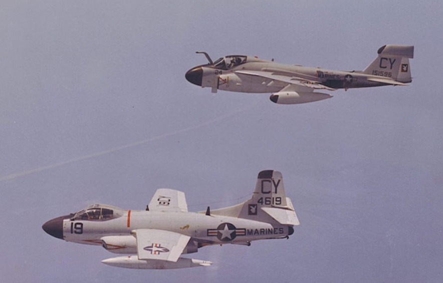
Dennis Jenkins provided some of the pictures; much of the information was taken from his excellent EA-6A/B monograph. Rick Morgan provided comments on the post, including: "I'm a firm believer that the EA-6A was the best jamming platform anyone used in Vietnam, having the best combination of frequency range, jamming strength and survivability. The Marines did great work with it."

In the late 1950s, the U.S. Marines initiated a program to modify obsolescent Douglas F3D-2 Skyknights, a two-place jet night fighter, for EW (electronic warfare) missions as a replacement for their propeller-pulled Douglas AD-5s. These F3D-2Q/EF-10Bs had limited performance in all respects but provided essential threat-radar reconnaissance and strike-mission radar warning and jamming at the beginning of U.S. combat involvement in Vietnam in 1965.

In the meantime, Grumman and the Marines created a program to develop a modification of  the new A2F (subsequently A-6) Intruder that had first flown in April 1960 for EW missions. The prototype EA-6A, BuNo 148618 that had been the eighth A-6A built, first flew in April 1963.

For in-depth coverage of both the EA-6A and EA-6B programs, two paperback monographs are recommended:

Both are available used for $10 plus shipping on Amazon. I prefer Jenkins' Aerofax Minigraph 7 as it is more complete from a technical perspective and up-to-date as of 1989 but Aerophile Extra Number 2 has more for the model builder, including reviews of kits available at the time of its publication, 1985. Jenkins subsequently posted an errata report.

The first six EA-6As were conversions of early production A-6As, BuNos 147865/148616/148618/149475/149477/149478 (not in order of acceptance; 147865, the second A-6A, was the last to be accepted as an EA-6A)

The next six EA-6As were redirects of A-6As on the production line, BuNos 151595-151600

The final 15 of 27 total were new builds, BuNos 156979-156993

A-6A BuNo 149935, the 21st A-6A, was used as an avionics test bed (NEA-6A); it is not included in the total of 27.


I'm going to limit this post to the major differences between the A-6A and the EA-6A and summarization of the various changes over time to the EA-6A's exterior and cockpit.

The major external differences were:

- Eight inches longer fuselage ahead of the nose landing gear and smaller radome

- A large blade antenna on the forward-facing nose landing gear door; this required that the landing/taxi and angle of attack lights be relocated on the door and the lower anti-collision light be relocated forward on the fuselage.

- Pylon provisions under the outboard wing (denoted "A" and "B") for a total of seven, originally to carry a large pod on a bespoke pylon (shown in the three-view drawing above) for passive ECM (electronic countermeasures) reconnaissance; only the first 12 EA-6As carried this pod. The location was subsequently used for a conventional multi-purpose pylon to carry other mission-related stores; according to Rick Morgan, as of 1979 A and B were only cleared for AGM-45 Shrike and ALE-32 chaff pod. "When FEWSG got the bird they added ALQ-167 and 170 jammers to the list.  ALE-41 and -43 chaff pods were eventually added as well."

- Third wing fence located outboard of the wing-fold joint (it was probably not aerodynamic but required to strengthen the wing aeroelastically for the utilization of the pylon on the outboard wing to carry stores)

- Deletion of speed brakes on the wing tips and retention of the fuselage-mounted speed brakes deleted from the A-6A

- A small air scoop on the top of the mid fuselage, a larger one beside it on the upper left side of the mid fuselage, and a small antenna fairing on the top of the fuselage forward of the scoops


Cropped from photos provided from Tailhook Association via Mark Aldrich

- A large antenna fairing on the top of the vertical fin (note that the two antenna fairings on both sides of the EA-6B vertical fin were not present on the EA-6A): this resulted in the upper anti-collision light being relocated to the aft end of the sliding canopy

At some point, the pitot was removed from the left wing tip and replaced by two pitots on either side of the top of the nose ahead of the refueling probe:

The DECM antenna mounted on a boom extending forward from the middle pylon on each wing was not originally present on some or all of the first 12 EA-6As and it was removed from the later RECAP aircraft.


The cockpit for the first 12 EA-6As:

Note that the left side of the instrument panel is virtually identical to the A-6A's and the right side, like the A-6A's, is farther aft since the right seat was farther aft and lower than the left seat for pilot visibility to the right.

A subsequent change in the mission equipment suite resulted in this EWO (electronic warfare operator) instrument panel:

Finally, 11 EA-6As went through a RECAP program which resulted in this cockpit configuration:

Note that in the picture of the pilot's instrument panel, the pilot's A-6A vertical display indicator has been replaced by a standard attitude director indicator and the left side of the WSO's instrument panel is visible.

The EA-6A crew was originally seated on Martin Baker GRU-5 seats. These were subsequently replaced by GRU-7 seats in the mid 1970s. The seats are similar in appearance but very different in detail, e.g. the parachute housing.

RECAP also resulted in external configuration changes. Among other details, the doppler radar fairing under the aft fuselage and the boom-mounted DECM antennas were removed, a small forward facing antenna was added at the base of the inflight refueling probe, an antenna fairing was added under each wingtip, and a small "beer can" antenna was added on the aft end of the fin-tip pod.

 Antenna on inflight refueling boom:

Antenna on the underside of the wingtip:


The RECAP BuNos were 148618/149475/151596-151600/156983-5/156987