Dennis Jenkins provided some of the pictures; much of the information was taken from his excellent EA-6A/B monograph. Rick Morgan provided comments on the post, including: "I'm a firm believer that the EA-6A was the best jamming platform anyone
used in Vietnam, having the best combination of frequency range, jamming
strength and survivability. The Marines did great work with it."
In the late 1950s, the U.S. Marines initiated a program to modify obsolescent Douglas F3D-2 Skyknights, a two-place jet night fighter, for EW (electronic warfare) missions as a replacement for their propeller-pulled Douglas AD-5s. These F3D-2Q/EF-10Bs had limited performance in all respects but provided essential threat-radar reconnaissance and strike-mission radar warning and jamming at the beginning of U.S. combat involvement in Vietnam in 1965.
In the meantime, Grumman and the Marines created a program to develop a modification of the new A2F (subsequently A-6) Intruder that had first flown in April 1960 for EW missions. The prototype EA-6A, BuNo 148618 that had been the eighth A-6A built, first flew in April 1963.
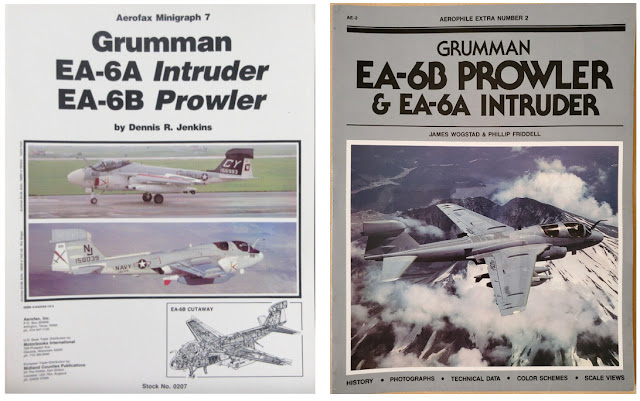
For in-depth coverage of both the EA-6A and EA-6B programs, two paperback monographs are recommended:
Both are available used for $10 plus shipping on Amazon. I prefer Jenkins' Aerofax Minigraph 7 as it is more complete from a technical perspective and up-to-date as of 1989 but Aerophile Extra Number 2 has more for the model builder, including reviews of kits available at the time of its publication, 1985. Jenkins subsequently posted an errata report.
The first six EA-6As were conversions of early production A-6As, BuNos 147865/148616/148618/149475/149477/149478 (not in order of acceptance; 147865, the second A-6A, was the last to be accepted as an EA-6A)
The next six EA-6As were redirects of A-6As on the production line, BuNos 151595-151600
The final 15 of 27 total were new builds, BuNos 156979-156993
A-6A BuNo 149935, the 21st A-6A, was used as an avionics test bed (NEA-6A); it is not included in the total of 27.
I'm going to limit this post to the major differences between the A-6A and the EA-6A and summarization of the various changes over time to the EA-6A's exterior and cockpit.
The major external differences were:
- Eight inches longer fuselage ahead of the nose landing gear and smaller radome
- A large blade antenna on the forward-facing nose landing gear door; this required that the landing/taxi and angle of attack lights be relocated on the door and the lower anti-collision light be relocated forward on the fuselage.
- Pylon provisions under the outboard wing (denoted "A" and "B") for a total of seven, originally to carry a large pod on a bespoke pylon (shown in the three-view drawing above) for passive ECM (electronic countermeasures) reconnaissance; only the first 12 EA-6As carried this pod. The location was subsequently used for a conventional multi-purpose pylon to carry other mission-related stores; according to Rick Morgan, as of 1979 A and B were only cleared for AGM-45 Shrike and ALE-32 chaff pod. "When FEWSG got the bird they added ALQ-167 and 170 jammers to the list. ALE-41 and -43 chaff pods were eventually added as well."
- Third wing fence located outboard of the wing-fold joint (it was probably not aerodynamic but required to strengthen the wing aeroelastically for the utilization of the pylon on the outboard wing to carry stores)
- Deletion of speed brakes on the wing tips and retention of the fuselage-mounted speed brakes deleted from the A-6A
- A small air scoop on the top of the mid fuselage, a larger one beside it on the upper left side of the mid fuselage, and a small antenna fairing on the top of the fuselage forward of the scoops
- A large antenna fairing on the top of the vertical fin (note that the two antenna fairings on both sides of the EA-6B vertical fin were not present on the EA-6A): this resulted in the upper anti-collision light being relocated to the aft end of the sliding canopy
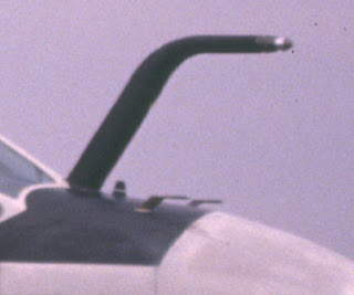
At some point, the pitot was removed from the left wing tip and replaced by two pitots on either side of the top of the nose ahead of the refueling probe:
The DECM antenna mounted on a boom extending forward from the middle pylon on each wing was not originally present on some or all of the first 12 EA-6As and it was removed from the later RECAP aircraft.
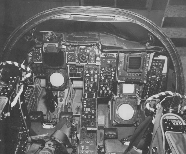
The cockpit for the first 12 EA-6As:
Note that the left side of the instrument panel is virtually identical to the A-6A's and the right side, like the A-6A's, is farther aft since the right seat was farther aft and lower than the left seat for pilot visibility to the right.
A subsequent change in the mission equipment suite resulted in this EWO (electronic warfare operator) instrument panel:
Finally, 11 EA-6As went through a RECAP program which resulted in this cockpit configuration:
Note that in the picture of the pilot's instrument panel, the pilot's A-6A vertical display indicator has been replaced by a standard attitude director indicator and the left side of the WSO's instrument panel is visible.
The EA-6A crew was originally seated on Martin Baker GRU-5 seats. These were subsequently replaced by GRU-7 seats in the mid 1970s. The seats are similar in appearance but very different in detail, e.g. the parachute housing.
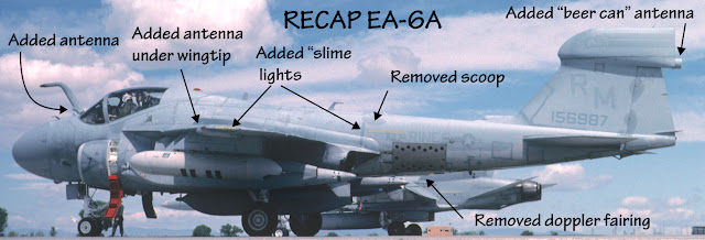
RECAP also resulted in external configuration changes. Among other details, the doppler radar fairing under the aft fuselage and the boom-mounted DECM antennas were removed, a small forward facing antenna was added at the base of the inflight refueling probe, an antenna fairing was added under each wingtip, and a small "beer can" antenna was added on the aft end of the fin-tip pod.
Antenna on inflight refueling boom:
Antenna on the underside of the wingtip:
The RECAP BuNos were 148618/149475/151596-151600/156983-5/156987


Great topic…and very thoroughly researched. One more thing worth mentioning is the interference plate installed on the rudder (also found on the Prowler).
ReplyDeleteLate in life, at least a couple of airframes (156984 and 156990) were seen with “towel rack” intelligence gathering antennas installed atop the fuselage (offset to the RH side).
ReplyDelete