Sunday, December 29, 2013

Things Under Wings: AERO Pylons


The smallest pylon was only capable of being loaded with rockets. A slightly larger one (Mk 55?) was then introduced that could carry both rockets and small (100-lb?) bombs.

Note that this AD-4 outboard wing panel has both types of small pylons.


This AD has the small pylons with 100-lb bomb capability as well as one large AERO 14A pylon that could be loaded with both bombs (up to 500-lb) and rockets.


Note that strictly speaking, AERO should be all capital letters, since it is an acronym for Aircraft Equipment Reference Ordinal...

Tuesday, October 22, 2013

Tuesday, October 1, 2013

F7F Tigercat Shell Ejection Ports

A question arose on a modeling web site about the location of the shell/clip ejection ports for the nose-mounted Grumman F7F .50 caliber machine guns. That turned out to be not very well documented. I also determined that because the narrow fuselage required that all four ammunition boxes be staggered, the pair of guns on the right side of the fuselage were located aft of the two on the left side, with the ejection ports positioned accordingly. (There was a longer blast tube on the right side so the ports in the nose were not staggered.)

Right side (XF7F-1 wind tunnel test)
Here is a better view of the location of the 20 mm cannon ports in the wing:
They appear to be pretty much in line with the barrels, maybe slightly outboard.

Left side (early F7F-1)
Note how much farther forward they are relative to the wing leading edge than those on the right side.

Saturday, September 7, 2013

F2H-2 External Stores

F2H-2 Ordnance Options

1,540-lb maximum; some examples on the SAC:

Eight 100-lb bombs or five-inch rockets

Four 250-lb bombs

Two 500-lb bombs

Four 250-lb bombs and four five-inch rockets


Some bombs were darkish green olive drab. The bands were generally yellow. The fuse in the nose was unpainted metal.

Note that tail fins, which were stored separately from the bomb body, were generally pristine since any distortion from rough handling affected accuracy.

Rockets also varied in the shade of olive drab. Again, the fins were generally pristine.

Tuesday, August 20, 2013

Half-baked 1/72nd Grumman WF-2/E-1B Conversion

Hasegawa produced an excellent kit of the S2F-1 (S-2A Stoof) with the later aft engine nacelles. Unfortunately, all the modification kits to produce the rest of the family, the Trader (TF-1/C-1 COD) and the Tracer (WF-2/E-1B Fudd), relied on the same inaccurate three-view drawings. The major error was the planform view of the radome for the Tracer. As it turns out, the Fudd also had a greater wingspan and more dihedral in the outboard wing panels although most of the outer wing panel structure of the Stoof was retained.
For more, see http://tailspintopics.blogspot.com/2010/11/trader-and-tracer.html

Having bought a few Mach II kits and only finished one (the F2Y Seadart, which wasn't too bad actually), I decided to use the Falcon conversion that is still available as of this date.

It's probably best to ignore the wingspan and dihedral differences and simply sand of the external hinges, fill the old fold line, and redo it with the Grumman sto-wing panel. However, I decided to model the kit with the wings folded: then Fudd tended to ride on the tail wheel, which was changed from the Stuff to be free swiveling. That eliminated the need to put weight in the nose, always hard to find enough places to do so in a twin prop, and the increase in chord of the wing center section. Nevertheless, it still requires extension of the outboard wings to get the right interface with the vertical fins when the wings are folded.
 
I did the wingspan increase two different ways: one with a plug, to utilize the inboard end of the outboard wing that resulted from very carefully cutting the wing along the fold line; and the other by creating an extension of the inboard end of the outboard wing that matched the outboard end of the center wing section. The decision to do it two different ways was deliberate: I wanted to see which was a better choice from a modification standpoint. Unfortunately, if there is an advantage of one over the other, I've forgotten.

The stub fin needs to be cut down as shown.
 
I've forgotten exactly how I produced a new trailing edge for the radome but it wasn't a big deal. I correct things that are obviously wrong and easy to fix and don't bother correcting errors that are not obvious and hard to eliminate. The radome planform is the former. Basically I added a piece of sheet plastic with the right shape of the aft part of the radome between the upper and lower halves of the Falcon radome. Then I completed the shape with putty.
 
 
I think the depth of the belly needs to be fixed as well, another legacy of those inaccurate drawings, but I stalled out before I got there. All I was going to do was build a "egg crate" with two longitudinal beams and three or four transverse ones cut from sheet plastic with the right added depth and curvature and fill in the pockets with putty or Apoxie Sculpt. I subsequently discovered that the fuselage cross section was more different than I thought (see the blog post referenced above) but I'd still ignore that except for the size of the cockpit side windows.

I felt the need to add a small extension on the horizontal tail with a bit of sheet plastic. I can't remember why but it may have been needed to get the correct span for the stabilizer or the right mounting angle for the vertical fin. The vertical fins must have been pretty close because I don't see any notable modification.
 
If I remember correctly, the kit instructions would have you cut the kit nacelle off too far forward.
(Note that the front strut of the landing gear hasn't been glued in so the gear could be "retracted" to prevent damage during construction and painting.)

The bulkhead between the cockpit and the cabin also had to be corrected.

And then I got distracted or something...
 

Tuesday, July 16, 2013

JATO

JATO stands for Jet Assisted Take Off. If that seems odd, since the concept utilized a rocket rather than a jet engine, it is also known as RATO. The first JATO takeoff in the U.S. appears to have been accomplished with a 174-lb thrust black powder rocket under an XPQ-13, which was an ERCO Ercoupe acquired by the Army. The test was accomplished at March Field in California.

A 50% reduction in takeoff distance was demonstrated, with the rocket burning for 12 seconds.

Both the Army and the Navy recognized the benefit that JATO could provide for a takeoff assist from short fields or for an overloaded airplane. The Navy was particularly interested in using JATO for carrier takeoffs in place of the catapult and for safer takeoffs of seaplanes from a restricted harbor or rough seas. A series of demonstrations were conducted with various carrier-based airplanes and seaplanes.


The bottles were generally mounted on three hooks, one to transfer the thrust of the JATO to the airplane and two to stabilize the bottle.
JATO was critical to the carrier navy's claim to a nuclear weapons delivery capability back when the bomb weighed on the order of 10,000 lbs.

It had also been essential for the takeoff of the P2V "The Turtle" on its record-braking long distance flight in 1946: http://thanlont.blogspot.com/2016/09/the-turtles-takeoff.html

 The original JATO bottles created a great deal of smoke. Improvements resulted in a standardized 1,000-lb thrust unit of 15 seconds duration that was relatively smokeless.

One post-World War II carrier application was for deck launching an AD Skyraider armed with a Mk 7 nuclear weapon.
This consisted of two 4,500-lb thrust units mounted to an adapter on the lower speed brake.

The Douglas A3D Skywarrior was provided with a major JATO assist, presumably for a deck-run takeoff if the catapults were out of service:
This consisted of 12 units with 4,500 lbs of thrust each.

One oddity of the A3D installation was that the usual arrangement of one thrust hook forward and two stabilizing hooks aft was reversed.
And somewhat curiously, the Air Force variant of the A3D, the B-66, had the standard arrangement.
However, this was just one more example of the myriad differences between the A3D and the B-66.

Note that the A3D and B-66 JATO provisions were permanent. The A4D could also be fitted with JATO for deck-run and short-field takeoffs, but this required the installation of dive brakes with JATO mounting capability.
Note that these mounts are the standard arrangement. The small hole in the side of the fuselage just forward of the speed brake is for the electrical lead used to fire the JATO.

One 4,500-lb unit could be mounted on each speed brake.
Note that the thrust line of the JATO unit is well below the center of gravity of the Skyhawk, providing a nose-up moment that augmented the sometimes inadequate one provided by the elevator and stabilizer trim.

One interesting aspect of a JATO-assisted takeoff is that the shortest takeoff distance, given the limited time of thrust, was achieved when the JATOs were fired so that they burned out just as highest obstacle for a non-JATO climb angle is cleared. This meant that they had to be fired at some predetermined point during the takeoff roll.

More, later...

Sunday, June 30, 2013

F4U-2 Antennas and Other Stuff

It doesn't take much to get me doing research on a subject of interest. In this case, it started out with the color scheme of the F4U-2 (see http://tailhooktopics.blogspot.com/2013/06/f4u-2-color-scheme.html) and segued to antennas. Unfortunately, I wasn't able to nail it all down to my satisfaction but at least I have some progress to report. Much of this has already been noted by Don Fenton on Hyperscale.

First, the F4U-2s were converted from some of the earliest production F4U-1s. In fact, the very first production F4U-1 was modified to be the prototype. As a result, some pictures show early Corsair features like the 360-degree cowl flaps. They subsequently received many changes before they deployed in addition to the unique hardware needed for the night fighter mission and probably some while overseas in combat. However, there was at least one exception to the "standard" Corsair configuration: the stall strip on the right wing leading edge doesn't appear on the deployed pictures of the VMF(N)-532 and VF(N)-101 airplanes.
And they might have had the taxi/landing light under the left wing, a feature on early F4Us and of benefit to a pilot flying at night from land bases:

As far as the cockpit goes, a three-inch diameter radar scope was added in the middle of the instrument panel directly under the gunsight, which was the original one with an integral reflector glass, and the bullet-resistant plate glass between the windscreen and gunsight was removed for improved visibility.
Obviously some of the instruments had to be rearranged, with the artificial horizon being moved to the left according to this mockup picture:
It looks to me like the artificial horizon was incorporated in a Sperry autopilot installation.

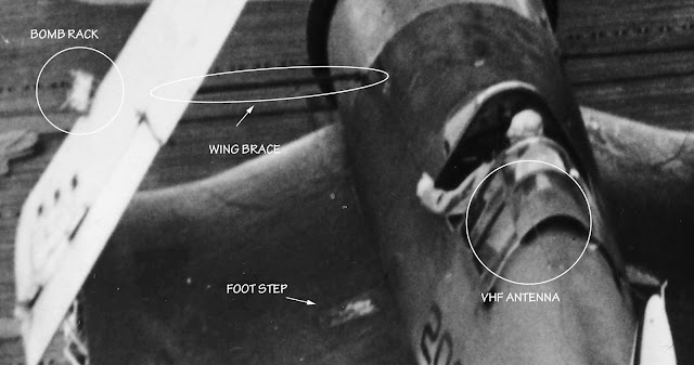
For some reason, the antenna mast was deleted and the bitter end of the wire antenna was terminated at the outboard end of the leading edge of the right horizontal stabilizer. A VHF radio was installed with its whip antenna on the turtleback mounted slightly left of centerline and angled left. An IFF whip antenna was mounted on the belly aft of the downward vision window. The radar altimeter required two identical antennas on the belly.

The radar altimeter antenna installation is one of the more confusing configuration details since these were at least initially mounted fore and aft of the downward vision window as shown here.

However, there don't seem to be any radar altimeter antennas in some pictures - they were probably only essential for carrier operations at night - and in others the two antennas are both mounted under the aft fuselage. My guess is that there were two alternatives (three when you count none being installed) as shown on this illustration along with other configuration details.

Some annotated pictures that might be helpful:
Note that the first picture is a VMF(N)-532 airplane as are all with 2XX side numbers. The second on is assigned to VF(N)-101, which provided detachments to Enterprise and Intrepid; these had one and low two-digit numbers. Pictures of the VF(N)-75 airplanes are scarce, as in I've seen one poor reproduction in a book.

Some F4U-2s had the armor added atop the rear of the canopy:

The biggest error in kits, including Tamiya's 1/48th F4U-2, is the radome. The fairing on the upper surface of the wing didn't taper in width as viewed from the top like subsequent wing-mounted radome installations. It didn't taper at all as it faired into the wing surface:
Don Fenton provided some guidance with respect to the Tamiya 1/48th F4U-2 kit in addition to what I've already noted above:
The 1/48 Tamiya F4U-1/2 kit has the outer wing panel fuel tank filler caps in the wrong position. Fill in existing and rescribe new ones same position but one panel line inboard. Add the handgrips to the caps if you want. And while you're at it, add the small vent tubes to underside of the wing. These go in the minute indention shown near the large rectangular hatch in the lower outer wing panel. These are characteristic of the wet wing Corsairs. Check page 23 D&S 55.
- Do not use the centerline fuel tank or Brewster bomb rack.
- Cockpit interior was painted black or Dull Dark Green, take your pick. The instrument cowl and interior of the windscreen was likely painted black.
- Use the salmon colored primer as you please for the wheel wells.
- Gear struts and the interior of the engine cowling likely remained Light Gray
- Paint over the downward vision window

For Dave Hansen's 1/32nd Tamiya build, see http://forum.largescaleplanes.com/index.php?showtopic=56654&page=1
and/or https://imodeler.com/2017/06/a-corsair-for-bob/ 

Friday, June 28, 2013

F4U-2 Color Scheme

The F4U-2 was (with a couple of exceptions) modified by the Navy from production Vought F4U-1 "birdcage" corsairs to be a night fighter.
The airplanes came from the factory in a blue-gray over light gray paint scheme. They were subsequently repainted by the Navy in the tri-color paint scheme before they were deployed.

Basically, the tri-color scheme required painting the top of the fuselage, wings, and horizontal tail non-specular sea blue; the bottom of the fuselage, wings (with an exception for that portion of the wings that folded upward) and horizontal tail non-specular white; and the vertical tail, the sides of the fuselage, and the bottom of wings that folded upward non-specular intermediate blue. The sides of the fuselage could be painted intermediate blue by either of two methods, A) by blending the non-specular sea blue and white so that the result on the side of the fuselage that was vertical approximated intermediate blue or B) by painting the side of the fuselage intermediate blue and blending it into the top and bottom color "without noticeable demarcation".

This is a head-on comparison of the factory blue-gray/light gray scheme (on an F4U-1 modified with the R-4360 for evaluation) versus the tri-color scheme:
Note that it's hard to believe from this picture that the vertical fin on the left is blue-gray and the one on the left is intermediate blue or that the bottom of the fuselage on the left is light gray and the one on the right is non-specular white.

This is an example of the Norfolk-type scheme:
 NASA Langley Image #EL-2000-00231 dated 31 July 1943

For a discussion of the Norfolk scheme, see http://tailspintopics.blogspot.com/2010/01/ww-ii-color-scheme-anomaly.html

There is an excellent illustrated article on the development of the F4U-2 and VMF(N)-532 operations by Richard Abrams in the Spring 1973 issue (Volume 18 Number 1) of the American Aviation Historical Society Journal. It is clear from the pictures that the -532 Corsairs were painted in a Norfolk-type scheme before deployment but over time the demarcation of colors and the colors themselves faded. (It appears that any F4U-2 with the side number 2XX is from -532.)

However, many illustrations (and some models) show F4U-2s over painted with black along the sides of the fuselage. Abrams states unequivocally that this was not so, although he may only have been sure about the initial paint scheme in general and VMF(N)-532 in particular. The existence of a non-standard scheme was probably based on these pictures of VF-101(N) F4U-2s being readied for take off from Intrepid. The paint scheme doesn't correspond to either the Norfolk scheme or the production Vought scheme.


Steven Eisenman has noted that there is an area of intermediate blue between the top and bottom colors on the cowl and aft fuselage, just much lower than usual on the Corsair:

Note that the vertical tail is almost certainly intermediate blue but the sides of the fuselage look darker than the top of the fuselage. Some have speculated that the sides of the fuselage were painted black, but if that were accomplished to reduce the visibility of the airplane at night, then surely the vertical tail would have been toned down as well. One possible explanation for the darker color on the sides is that it was the result of a repaint following the removal of the red surround on the national insignia with the original sea blue having faded. However, that doesn't explain the complete lack of color differentiation on the cowling. Another is that the method A was used to paint the side of the fuselage without bothering to blend the sea blue and white very much...

Dave Hansen notes that the F4U-2 pictures above were the VF(N)-101 detachment aboard Intrepid. The squadron decal on the right side of the fuselage just below the windscreen was removed when a VF(N)-101 detachment went aboard Enterprise. He also reported that these airplanes had received the additional armor plate atop the very rear of the canopy.
In his opinion, the side of the fuselage was freshly painted semigloss sea blue. For his 1/32 Tamiya build, see http://forum.largescaleplanes.com/index.php?showtopic=56654&page=1