2 September 2025: I added some detail on the auxiliary air doors.
18 November 2016: For a note on F-4K XT-595 first flight markings, see http://tailhooktopics.blogspot.com/2016/11/f-4k-first-flight-markings.html
17 November 2016: I apparently noted but forgot to add this excellent description of empennage detail differences: http://phantomphacts.blogspot.com/2014/05/differences-between-phantom-fg1-and-fgr2.html
11 October 2015: Added additional information about engine inlet change
10 October 2015: Added nose landing gear illustration of difference between J79 and Spey F-4K/FGR.1 Phantom
21 February 2014: I added a comparison of the difference between the boundary-layer-removal hole patterns on the forward variable ramp.
15 December 2013: I added some more information on the fuselage changes and the afterburner shroud.
13 December 2013: I added some information about the F-4K changes required so it fit on the elevators of the British carriers.
11 December 2013: I revised the comparison of the area aft of the afterburner nozzle to show that the absence of a "step" in the upper line of unpainted metal was on the prototypes XT595 and 596 and the first production F-4K, XT857 only. The M prototype retained the step.
Note that I refer to the Spey-powered Phantoms as the F-4K and F-4M instead of FG.1 and FGR.2 respectively, the proper British designations.
The key points are these:
1. Air inlet width increased by three inches on each side (Derek Bradshaw). Note that the original inlets were about 43" deep and each had an inlet area of 500 square inches. Widening an inlet by only three inches would increase the inlet area by about 25%, somewhat more than the reported increase of 20%.
2. Afterburner shroud outside diameter of 43 inches; diameter of shroud at aft edge, 38.5 inches (from the circumference measured by Rob as reported on Britmodeler)
3. Wider and higher "nacelles" (bulkhead comparison drawings from Craig Kaston)
3. No change in wing span: the location and width of the trailing-edge flaps did not change and their inboard edge established the width of the F-4K/M fuselage at that point (as measured, the F-4K/M fuselage was slightly wider at the trailing edge of the wing)
4. No change to fuselage aft of the arresting hook attachment except that the outer mold line of the heat-resistant shingles was lowered and extended forward to fit the Spey afterburner shroud.
5. Increase in angle of incidence of the engine installation from 5.2 degrees (J79 measured on McDonnell drawing) to 6.75 degrees (F-4K/M specification)
6. The aft Sparrows were mounted the same distance apart as in the J79-powered Phantoms but were angled at 3.75º nose up consistent with the increase in depth of the lower aft fuselage
Note: It has been reported that the F-4K/M stabilators had reduced anhedral. This is incorrect; they had the same anhedral as every other Phantom.
A common error is to assume that the lower auxiliary air doors on the F-4K/M are in the same location as on the J79-powered Phantoms; they are not. See bottom view illustration.
I've used McDonnell-generated data, three-view drawings, lines drawings, and illustrations to create the comparison shown below, using the pretty-good McDonnell Blue Angel F-4J drawing as a baseline. Unfortunately, although it otherwise adheres pretty closely to the McDonnell B/J lines drawing, it is not exactly correct with respect to the longitudinal location or size of the J79-GE-8 engine afterburner.
An excellent set of walk-around photos of F-4M (FGR.2) XV497 by Graham Platt can be found here: http://www.britmodeller.com/forums/index.php?/topic/234949864-mcdonnell-fg1-fgr2-phantom/
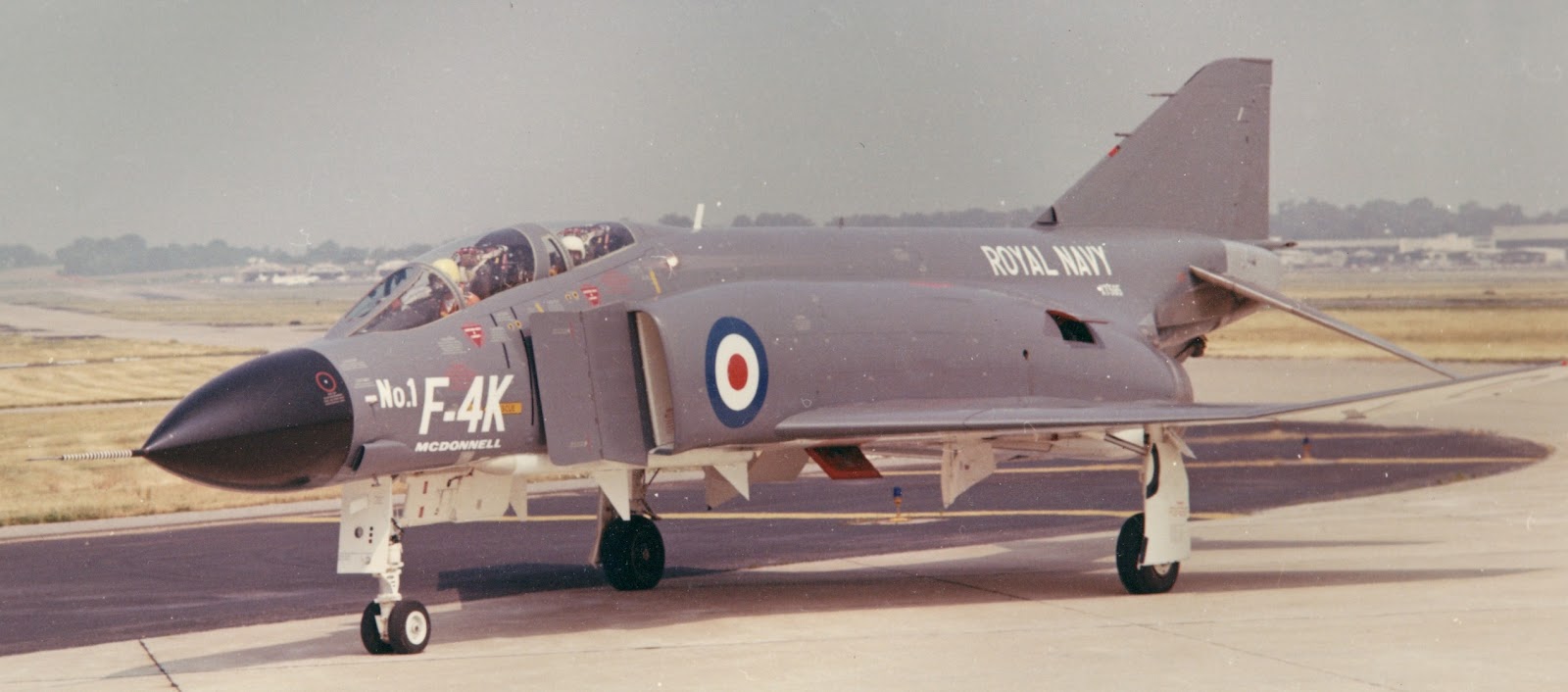
Although photos have limited use in establishing much more than basic shape or position relationships, this picture of XT-595 is as good a side view as you'll see:

The Spey was bigger around than the J79 because it was a bypass engine and had a higher mass flow. The air inlet and engine "nacelle" were enlarged accordingly, the former in width and the latter in width and height. Since the relationship of the thrust line to the location of the airplane's center of gravity is pretty important and McDonnell apparently didn't want to change the location of the arresting hook or make any significant changes to the fuselage aft of station 515 (subcontracted for the F-4K/M to Short Brothers), the Spey had to be installed at a slightly greater angle than the J79, requiring a deepening of the lower aft fuselage. (Other considerations as to engine location were the weight/cg of the Spey versus the J79 and the effect of the exhaust on the flow field around the stabilator.) Close examination of photos leads me to conclude that the top of the Spey's afterburner shroud was located at or very slightly below the top of the J79's afterburner and the inboard sides of the two engines were probably the same distance from the fuselage center line (note the weasel-wording).

The afterburner shroud moved aft to position the afterburner "petals" fully open for afterburner operation and forward when the afterburner was shutdown.

The red area in the following illustration corresponds to the dip in the fastener line in the next illustration.


A fairly direct comparison of a J79-powered fuselage with the F4K/M was obtained from the Robert F. Dorr collection:

Note the additional auxiliary air door on the side of the aft fuselage and the low-pressure compressor bleed port just ahead of and below it. Both are shown in red on the side view illustration. When the aircraft was shut down, these gradually drooped to just barely open.
These doors served two purposes. At low speed and on the ground, they provided additional cooling air to the engine compartment. At very high speed, they relieved pressure in the engine compartment greater than 10 psi above ambient by opening when the pressure exceeded the ability of a door's actuator to hold it closed. The actuation of the doors was different between the J79 and Spey-powered F-4s: the former (which were only on the bottom of the fuselage) opened when the gear handle was down and at high engine compartment pressure in flight; the latter (all four) were controlled by airspeed and open below 210 knots as well as at high engine compartment pressure in flight.
Another example is this side-by-side picture taken aboard Independence in 1975:


Another set of changes required for compatibility with the British carriers was a folding radome and shorter fuel vent.


The fuel vent was shorter and the outlets modified into a shallow "V".

I think the bottom line is that modifying an F-4J kit into an F-4K or F-4M model is doable but may involve more changes to the fuselage than most would want to make. Frank Mitchell is not one of those people: http://hyperscale.com/features/2002/fgr2fm_1.htm
"Chek" brought another difference to my attention that I hadn't noticed. The hole pattern on the forward variable ramp (the holes suck off the slow-moving boundary layer air) is different between the F-4B and subsequent J79-powered Phantoms and the Spey-powered ones:

The inlet ramp and inlet itself were changed as well. Because the inlet was widened by three inches, its lip was moved aft about four inches to keep the shock off the leading edge of the fixed ramp properly positioned on it at supersonic speeds. Moving the inlet lip back necessitated moving the leading edge of the variable ramp (which was hinged to the trailing edge of the fixed ramp) back about three inches for the same reason. This meant that both the fixed and variable ramps were slightly wider.
More later...

Hi Tommy, I always follow your Phantom articles with great interest and admiration for your research. Despite an active interest going back to the first FGR2(F-4M)landing here at Aldergrove in July 1968, you always seem to have some new information to reveal.
ReplyDeleteRegarding your F-4J/K composite side view drawing, I would draw your attention to lowering of the upper outline of the exhaust nozzle with respect to the J model. Photos of the area show a 'filler keel' area as a darker titanium area, which well shown in your F-4K photo at: http://tailspintopics.blogspot.co.uk/2011/05/early-phantom-iis-redux.html. I also posted some useful construction photos from Michael Burns' book in this thread: http://forum.largescaleplanes.com/index.php?showtopic=37887&st=105 which show the lowered cross section clearly.
I hope you find the info of some use - an accurate large scale Spey Phantom is sorely needed!
Hi, interesting stuff...
ReplyDeleteTge jet pipes exit at quite a downward angle, were the engines mounted at an angle, or was there a bend in the jet pipe?
Cheers, Scott
The engines were mounted at an angle like they were in the J79-powered Phantoms...
ReplyDeleteWhen I was 57FIS in Keflavik, other units would come pull alert with us from time to time. The Brits brought some gorgeous Spey Phantoms to play with us once during my '80-82 tour, and were a welcome addition to the line.
ReplyDeleteWonderful article. Just as a point of interest, with reference to the photo of the FG1 launching on the Independence , the Spey powered Phantoms were too hot to use the blast plates. The initial trials on HMS Ark Royal in the 60's had to stop as the flight deck was melting. Even after the flightdecks were modified firesuit men would have to cool the deck with fire hoses after each launch. The extended nose wheel was for a greater "angle of attack" from the main wings allowing for a better take off from carriers.
ReplyDeleteExcellent article!
ReplyDeleteAside from the general differences between the J79- and Spey-powered Phantoms, there are some other interesting distinctive features of the the F-4K and F-4M. Both FG.1 and FGR.2 used different stabilisers. The F-4K had the slotted stabilators whereas the F-4M featured the fixed leading edge stabilisers.
However, the rear fuselage of the F-4M featured a rather unconspicuous, yet unique set of altered arresting gear servicing access doors. An enlarged (almost twice the size) #61 access door on the port tail boom and the addition of a dedicated #61R access door along with a repositioned and reshaped #62 arresting gear filler point. IIRC, the latter arrangement cannot be found on any other variant of the F-4.
FGR.2 Arresting Gear Servicing Doors:
http://i102.photobucket.com/albums/m98/Airfixer1970/ARC/arrgear_doors_zpsamdwioml.jpg