Wednesday, December 7, 2016

Vought F6U Pirate Trivia

The F6U catapult hook mechanism (and hold back, not shown), located aft of the nose-landing-gear well, was retractable and covered by two access doors.
One of many changes during the Pirate's development was to add a link/case chute on the belly, directly under the catapult mechanism location, to channel the links and cases from two of the cannons aft, safely past the engine intakes.


So what happened to the catapult mechanism or its access? After more closely examining a picture of the F6U bailed to NACA up on jacks and a closeup picture of the chute itself, I realized that there were actually two side-by-side chutes, each mounted on one of the catapult access doors.


For more on the F6U and the Admiral kit: http://tailspintopics.blogspot.com/2013/03/vought-f6u-pirate.html

Monday, November 28, 2016

XF-92 Main Landing Gear Actuator

Photobucket is fighting me today so I'm posting this picture here for an answer to an XF-92 question on Britmodeler.
 Annotated Howard Mason Photo

The landing gear actuator is at the aft end of the wheel well. There are other pictures of it here:
http://www.primeportal.net/hangar/howard_mason3/xf-92_dart/

It acts on a bellcrank that rotates the landing gear up and down. Note that the actuator is fully retracted when the gear is down so no piston is showing as when an actuator extends to put the landing gear down. Note the slot in the actuator end fitting that is connected to the bellcrank for the latter to slide inside it as actuator extends fully as the gear retracts. In other pictures on the link you'll also note that the hydraulic lines are missing but the requisite hydraulic fittings are on the actuator.

Wednesday, November 23, 2016

Douglas Flight Test Logo


And on an XF4D overlaid on what appears to be a black circle based on a very tiny color image:


Tuesday, November 22, 2016

Grumman F7F Tigercat Variations

Annotated scan of the profiles in Squadron/Signal Publications Aircraft No 79, F7F Tigercat in Action:

Friday, November 18, 2016

F-4K First Flight Markings

I'm pretty sure (although I was there, I didn't notice it at the time) that the F-4K first-flight markings were not the same on the left and right sides.

The right side of XT-595 was marked "McDonnell" in red outlined with white and a big " NO. 1 F-4K" underneath that.

This was subsequently painted over.

I'm pretty sure that the left side did not have the markings on the mid fuselage. Instead, a small "McDonnell" and "No.1 F-4K" were marked on the nose, I believe using temporary paint that was subsequently washed off.

 RAM Decals 72-001 includes the markings for XT-595 (http://www.rammodels.co.uk/product_info.php/products_id/358/osCsid/a7a1df94887553fc4e1decf0e9b5011f); note that they have assumed that the markings were symmetric and therefore present during two different time periods, which I think is incorrect.

There were at least two small difference between XT-595 and production F-4Ks: the rear cockpit had throttles (but not stick or rudder pedals) and the fuel vent aft of the rudder was 'flat" rather than the V configuration (see http://tailhooktopics.blogspot.com/2012/05/spey-powered-phantom-changes.html and scroll way down). It also had the Mk 5 M-B ejection seats with the metal sugar-scoop parachute containers; I'm not sure when the Mk 7 was introduced.

The flight test team included me, easily identifiable as the youngest member, only a month or so out of college.
Joe Dobronski, newly promoted to be Chief Test Pilot, is in the sport coat on the far left; Bud Murray, who was the F-4K project pilot, is in the flight suit.

Joe's book, A Sky Full of Challenges, is only available from Amazon as an expensive used book.

It used to be available directly from him (see http://www.omnishops.com/TestPilot/) but Joe died last year and the link to order doesn't work. However, it appears to be available as an ebook: see https://www.smashwords.com/extreader/read/142339/1/a-sky-full-of-challenges

Sunday, August 28, 2016

F9F Panther Catapult Hook Up

The F9F Panther's catapult hook was retractable and located in the "notch" between the aft end of the speed brakes.
It can just be seen in this photo between the heads of the sailors hooking the pendant to it.
The holdback was attached to a retractable hook on the belly aft of the main landing gear.
Put it all together...

Sunday, July 24, 2016

X-47B Nose Gear Door Logos


The two seals on the forward end of the door on the second line are "zaps" from two carriers that the X-47B flew from, Roosevelt and Bush. The remainder are company logos.


Monday, June 20, 2016

Air & Space FH-1 Phantom Pictures


Note belly tank attach points (red)


Note recess for JATO bottle attachment...


Wednesday, April 13, 2016

Piasecki HUP Interior

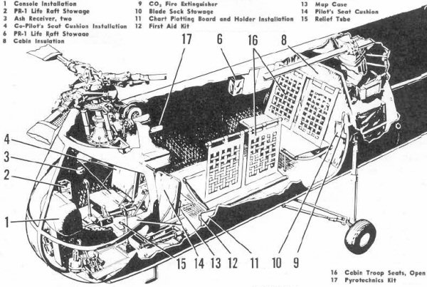
The HUP was somewhat underpowered so an interior might be somewhat less well furnished than shown here:


The rescue hoist was mounted above the right front seat and the rescue hatch below it so it had to be removed or folded forward for hoist operations:
Note that the flight controls including the cyclic, as shown above, might remain in place but the seat could not be folded forward unless it was removed.


 However, the pilot and crewman had to be insure that the rescuee didn't grab the controls as he came into the cabin.

There were several instrument panel arrangements. The top one was BuNo 128503-128600.


The cabin interior ended at the attachment point for the aft main landing gear strut;

The engine was mounted aft of the hole in the bottom of the fuselage and backwards, so the drive shaft pointed aft and the engine exhaust stack was forward of the engine.

The engine was mounted at an angle and drove a gearbox that had outputs forward to the front rotor and upwards to the aft rotor.
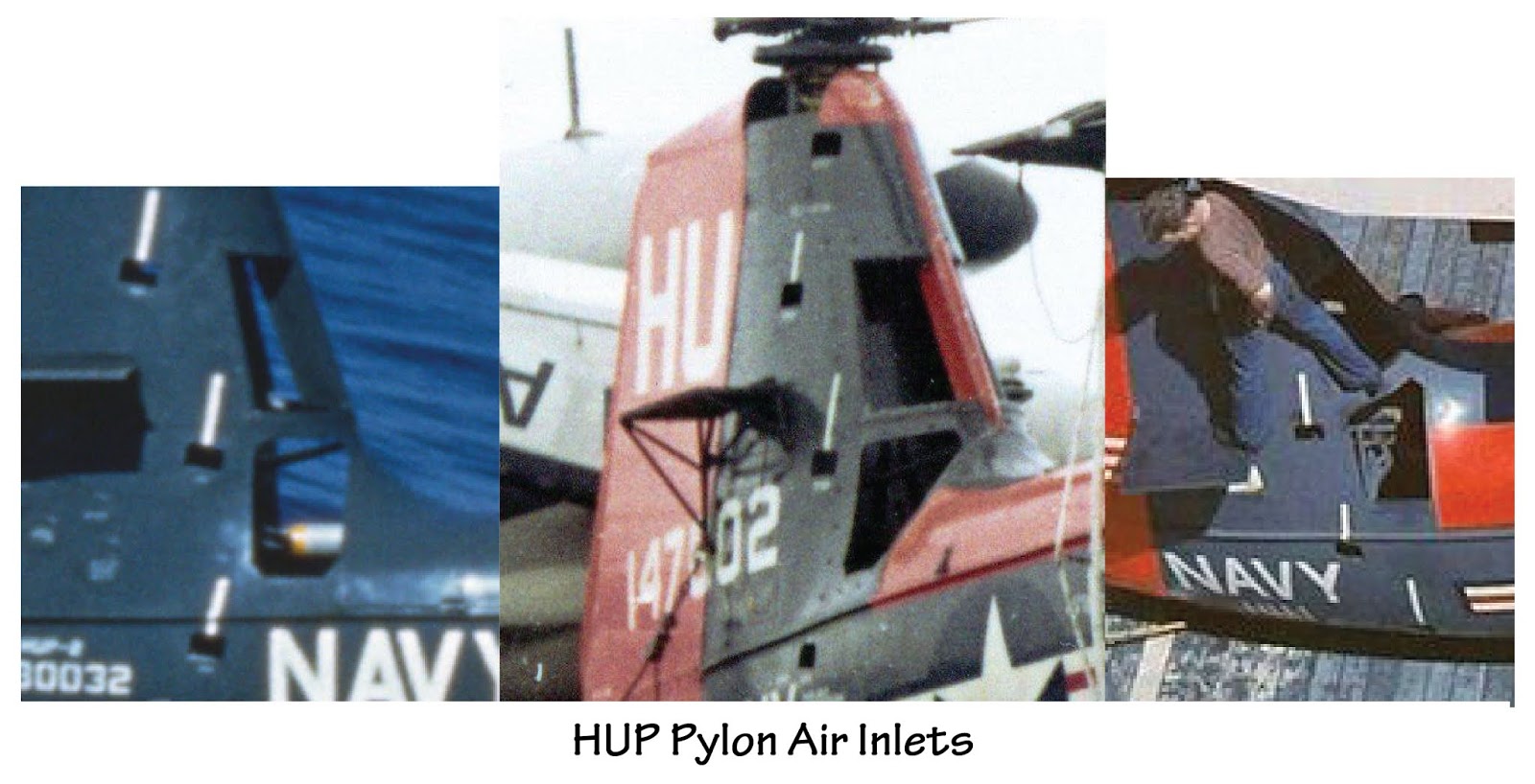
The engine was encased in a shroud. There was a fan on the "front" of the engine that sucked air in from the openings in the front of the pylon for engine cooling. The air exhausted out the opening in the bottom of the fuselage. An oil cooler was mounted at the rear of the opening.

The above inboard profile was created before the second pair of air inlets was added to the leading edge of the pylon and it appears to have an early version of the trailing edge of the fin. (The second pair of air inlets was added to leading edge of the HUP's aft pylon after it first entered service in order to increase cooling air to its hard working radial engine mounted in the fuselage.) The opening looks like a rounded rectangle from the side but because of the airfoil shape of the pylon cross section and the pylon's interface with the fuselage, it looks very different when viewed from other angles.

As a result, some kits have gotten the shape of the opening wrong.

This fuselage stations drawing can't be strictly relied on for shape but the station dimensions should be accurate (the overall length of the "shadow" on the ground was 31' 11"):

 Or a bit less as shown on this three view;
Note the shape of the rotor blade on the three view above. There were three different rotor blades. The first type had a tapered rounded tip as shown on the three view. The second had a constant chord of 1' and the outboard section was slightly twisted leading edge down with no taper. The third may be the same the same as the second in overall shape but was all-metal rather than being a wood-covered steel tube.
As far as I know, the rotor diameter was 35' for all blades.

The HUP-3s were H-25s built under contract to the Army. Fifty were delivered to the Navy instead. The H-25s had a slightly different interior and a different rotor head; the Navy may have installed the HUP rotor heads at some point.
(My guess is that the difference was the need for droop stops to keep the rotor from flapping excessively during startups and shutdowns on an aircraft carrier making a relatively high wind over deck for airplane takeoffs and landings.)

Another difference was that some H-25s (51-16577 and 51-16584 and subsequent) had a fairing on the right side of the fuselage associated with the field litter installation ( seen here under the side number of HUP-3 BuNo 147602):
 

For an excellent in-box review of the Amodel 1/72 HUP kit, see http://alexsmodelling.blogspot.ru/2017/03/hup-retriever-amodel-kit-review.html

Gordon Hewstone built the Siga 1/72 UH-25B kit: "It's a relatively crude kit to which I added a few details such as the lights and wiring on the landing gear".


Monday, February 15, 2016

Early P2Vs

Some odds and ends on the differences between the P2V-3 and the P2V-7...

P2V-3 Gun Nose:

P2V-3 Gun Nose vs. P2V-7 forward fuselage:

P2V-3C forward fuselage (significant differences in red) versus P2V-7 (the P2V-7 nose looks a bit off):
Note that for the P2V-7, the bomb bay was bulged downward (a change introduced with the -5), the nose landing gear moved forward to accommodate a bigger radar on the belly, and the canopy raised and relocated forward.
P2V-7 Nose Turret

The P2V-5 nose turret may be similar but the -5 did not have the raised canopy or the forward nose wheel well. (The forward end of the -5 wheel well was at Sta 114, 25" aft of the -7's.)

P2V Tail Turret

Note the rotation of the unit that was introduced at some point early on as a 2° downward rotation of the aft fuselage beginning about half way between the leading edge of the vertical fin and the leading edge of the horizontal stabilizer (it also resulted in the tilting aft of the vertical fin).