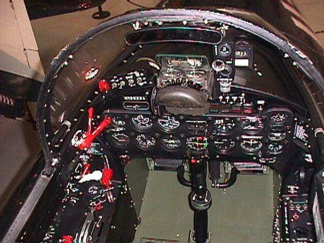
This is a hedge podge of pictures. The first four show the color of the ejection seat, which is pretty clearly interior green with a black headrest. Note that the headrest is tipped forward in the second and fourth one.
Note that this Panther has the additional white fiberglass reinforcement around the edge of the canopy and on the "strap" over it, unlike all the others in this post.
This is the cockpit of a restored Panther but it looks about right from a color standpoint. Note that the seat cushion and parachute were generally not removed from the airplane.
The next two pictures show the area aft of the armor plate.
Thursday, December 20, 2012
Friday, December 14, 2012
Early F4H RAT
Since this is not likely to be a subject of general interest, I am posting it here for those who have a desire to know.
The first F4H and a few after that had two Ram Air Turbines (RATs), one under each inboard wing leading edge. In this early flight picture, they are deployed.
This picture shows the location of the door.
The door opened outboard and the RAT dropped down from the compartment it covered.
This shows the RAT in the right wing in the extended position.
As shown above, the RAT was two-bladed and probably looked something like this:
When it was determined that inboard leading edge flaps had to be added for increased low-speed lift, the wing-mounted installation was no longer possible and a single RAT was incorporated in the upper left fuselage.
The first F4H and a few after that had two Ram Air Turbines (RATs), one under each inboard wing leading edge. In this early flight picture, they are deployed.
This picture shows the location of the door.
The door opened outboard and the RAT dropped down from the compartment it covered.
This shows the RAT in the right wing in the extended position.
As shown above, the RAT was two-bladed and probably looked something like this:
When it was determined that inboard leading edge flaps had to be added for increased low-speed lift, the wing-mounted installation was no longer possible and a single RAT was incorporated in the upper left fuselage.
Wednesday, December 12, 2012
FJ-4 Detail Under Canopy
FJ-4 with North American seat
FJ-4 with Martin Baker seat
Also see http://thanlont.blogspot.com/2011/02/transition-to-martin-baker-ejection.html
FJ-4 with Martin Baker seat
Also see http://thanlont.blogspot.com/2011/02/transition-to-martin-baker-ejection.html
Tuesday, December 4, 2012
S2F Overhead Hatch
Once again, I have overlooked the obvious. Not only do I know that the hatches over the S2F pilot and copilot slid inside and aft, I have sat in an S2F-1 and flown a Turbo Firecat. But in looking for illustrations/pictures of the open hatch for a response to a question about them, I suddenly realized that there isn't enough distance behind the aft end of the hatch and the bulkhead for the pilots for the hatch to slide open.
(Both pilots are showing both hands away from the controls while a red shirt is arming or disarming stores on the wing pylons.)
The answer is that it slides into a small compartment in the bulkhead. The dashed line on this illustration of the bulkhead behind the pilots shows approximately where the lower side of the compartment is.
S2F-1 MAD/Sonobuoy Crew Position
The following are from Calum Gibson's website (http://a4-alley.x90x.net/models/Walkarounds/Tracker.html) and used with his permission:
Here is a Bill Spidel picture of the hatch in the closed position that I was able to lighten enough to show the actuating mechanism and the track the hatch slid on. Rotation of the T-handle lowered the hatch and then it could be slid aft.
And in response to another question, the overhead windows were tinted green, although I don't know when that practice began. (The hatches were solid initially.) Alan Weber, who worked on civil S2Fs used for fire fighting: "in fact I never saw one first hand that wasn’t. We had stacks of them in our parts room and they all were tinted green."
* In the utility conversions where the equipment was removed and the seats mounted facing rearward more towards the cockpit, the hatch compartments were usually covered with interior quilting. In this case, the right side is uncovered.
(Both pilots are showing both hands away from the controls while a red shirt is arming or disarming stores on the wing pylons.)
The answer is that it slides into a small compartment in the bulkhead. The dashed line on this illustration of the bulkhead behind the pilots shows approximately where the lower side of the compartment is.
Alan Weber provided a picture of an S2F cockpit display that shows the compartment the hatches slid into.
Note that because of the length of the passageway between the cockpit and crew compartment, the aft end of the hatch hole cannot be seen in the crew compartment.*
S2F-1 Radar Crew Position
The following are from Calum Gibson's website (http://a4-alley.x90x.net/models/Walkarounds/Tracker.html) and used with his permission:
Here is a Bill Spidel picture of the hatch in the closed position that I was able to lighten enough to show the actuating mechanism and the track the hatch slid on. Rotation of the T-handle lowered the hatch and then it could be slid aft.
And in response to another question, the overhead windows were tinted green, although I don't know when that practice began. (The hatches were solid initially.) Alan Weber, who worked on civil S2Fs used for fire fighting: "in fact I never saw one first hand that wasn’t. We had stacks of them in our parts room and they all were tinted green."
* In the utility conversions where the equipment was removed and the seats mounted facing rearward more towards the cockpit, the hatch compartments were usually covered with interior quilting. In this case, the right side is uncovered.
Friday, November 30, 2012
SB2C-5 SAC Sideview
The following are the same drawing. The first one is the way I usually do these illustrations, with a dimensioned box that can be used with a copier that scales the copy to the desired size. The other two can also be downloaded. One will probably turn out pretty close as printed out. 

Thursday, November 29, 2012
F-4 Stabilator
The F-4 stabilator pivoted from a point above the surface of the stabilator at its juncture with the side of the aft fuselage. The necessary opening was covered by a plate that moved with the stabilator. Note that the top of the plate was not quite parallel with the upper surface of the stabilator.
(The Phantom in this case is a YF-4K. The colored lines are a temperature-sensitive paint that changes color at a specific temperature.)
A view from the other side, this time on an F-4A (the stabilator has the cambered leading edge modification):
A view from the side with the cover plate removed:
Drawn from pretty good McDonnell data and drawings, including check of 35 degrees sweep at 1/4 chord. Does not include leading edge slat. Outline shown "true", not a top view.
(The Phantom in this case is a YF-4K. The colored lines are a temperature-sensitive paint that changes color at a specific temperature.)
A view from the other side, this time on an F-4A (the stabilator has the cambered leading edge modification):
A view from the side with the cover plate removed:
This picture and the one below were taken and provided by an anonymous contributor
And a view from behind and below looking up and forward showing the carry-through structure covered by the plate and the stabilator actuator.
Revision A:
USAF stabilators were eventually modified with a blunt arrowhead-shaped reinforcement plate at the forward juncture of the inboard and outboard panels. This appears to have been introduced with the addition of maneuver slats on the F-4E (see http://modelingmadness.com/scott/viet/us/standf4.htm). However, there was no similar reinforcement associated with the similar maneuver slats introduced on the Navy F-4S (see http://tailspintopics.blogspot.com/2012/12/f-4s-wing.html.) There are indications that a reinforcement was added to this area on some Navy Phantoms, but it was probably a standard repair rather than a required modification at overhaul or in spares production. There are reports of Navy Phantoms with the USAF reinforcement but these may just be the use of a stabilator from USAF stock.
Sunday, November 25, 2012
Subscribe to:
Posts (Atom)