Somebody asked for details on the TBU/TBY wing fold area because it isn't covered in detail in Steve Ginter's monograph. Note that there are two hinge points, one on the main spar and one on the forward spar, and a large bellcrank that is driven by two actuators, one in the inboard wing and the other in the outer.
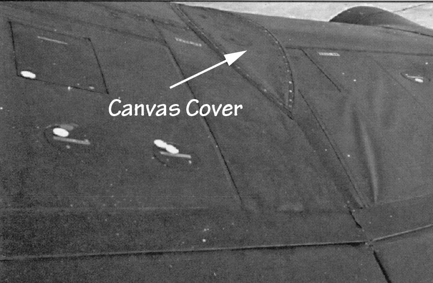
There was one confusing element, an oval panel with pointed ends on the upper surface of the wing over the wing-fold area. The panel was necessary to provide an opening for the outer wing to fold past vertical.
I initially assumed that the panel was metal and part of the outer wing but I couldn't figure out how it didn't interfer with the hinge on the main spar. I finally realized that it was something like canvas (perhaps a rubberized fabric) and simply folded in on itself.
Here the cover appears to be bulging upward from aerodynamic pressure in flight.
This illustration shows the location of the main spar hinge relative to the forward hinge point and the cover
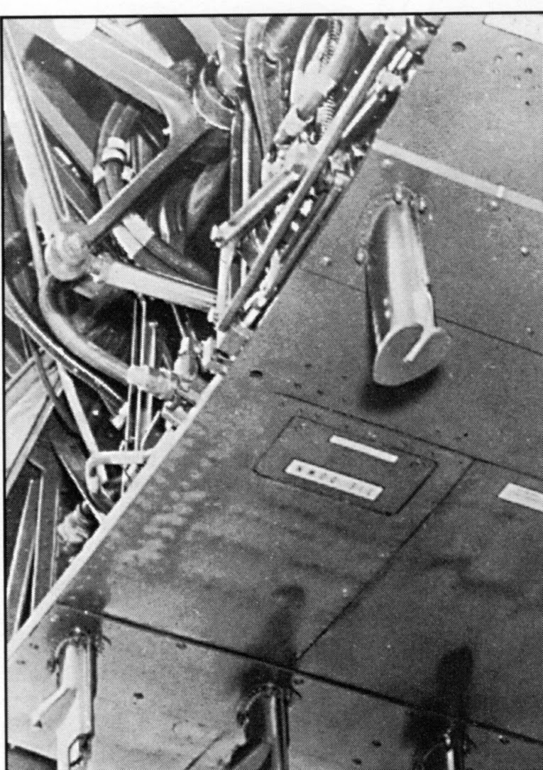
This was the only other picture that I could find of the fold area. It shows the lower half of the wing-fold actuator bellcrank and the inboard actuator.
Friday, March 27, 2015
Monday, March 9, 2015
F8U Underwing Details
There isn't much to be seen under the wing of an F8U when it is raised, even the underside of the wing itself.
Note that there was only one actuator to raise and lower the wing (the F8U-3 had two).
The top of the fuselage can barely be seen although this is what it looks like with the wing removed, looking forward from the pivot point.
There's a lot of white overspray on this derelict fuselage. The forward bulkhead should be red. The duct on the right side is covered with a silver insulation. Some of the piping was green zinc chromate. There is also a red fuel filter or something along the right forward side.
Tom Weinel has done some research and concluded that the area was green up through the early 1960s (e.g. F-8Es) and then painted white during Navy overhaul at some point or when the F-8s were rebuilt by Vought.
Note that there was only one actuator to raise and lower the wing (the F8U-3 had two).
The top of the fuselage can barely be seen although this is what it looks like with the wing removed, looking forward from the pivot point.
There's a lot of white overspray on this derelict fuselage. The forward bulkhead should be red. The duct on the right side is covered with a silver insulation. Some of the piping was green zinc chromate. There is also a red fuel filter or something along the right forward side.
Tom Weinel has done some research and concluded that the area was green up through the early 1960s (e.g. F-8Es) and then painted white during Navy overhaul at some point or when the F-8s were rebuilt by Vought.
Tuesday, January 6, 2015
Lockheed XP-80
24 January 2015 Update: There continue to be questions about the topside color based on close examination of the color photos of the prototype in the Air and Space monograph. However, Dana Bell is of the opinion that it is most likely Army Air Forces Dark OD but possible that it is RAF Dark Green or ANA OD.
19 January 2015 Update: Bob Sikkel noted that the horizontal stabilizer data for the XP-80 and the P-80A were the same so my overlay of the P-80A stab appeared to be incorrect. It turns out that I had used an inaccurate drawing for the overlay. I've revised the top view with one that matches the data.
9 January 2015 Update: Bob Sikkel, who got me interested in this project in the first place, provided the link to another walkaround that provides excellent pictures of the landing gear, among other things: http://aircraftwalkaround.hobbyvista.com/p80/p80.htm
8 January 2015 Update: It turns out that the color scheme as reported in the monograph that I relied on was incorrect. I've updated the following accordingly.
The Lockheed XP-80 was a one-off prototype powered by a different engine than the P-80A and subsequent Shooting Stars. It was a bit shorter and lighter than the P-80A. This photo was taken in conjunction with the first flight.
The more powerful but heavier engine required rebalancing the airplane by extending the fuselage forward. It probably allowed an increase in internal fuel as well since the main fuel tank was located in the fuselage between the cockpit and the engine.
Gerry Asher, aka Fox Three, described his conversion in the April 2001 issue (Vol 23 No 3) of Scale Aircraft Modeling. I don't think that he had the benefit of the National Air and Space Museum monograph on the P-80 Shooting Star.
The monograph includes a three-view of the XP-80 as well as several pictures, including some of the cockpit and some taken during the restoration process.
The difference in overall length between the XP-80 and the P-80A was 20 inches but the location of the aft end of the tail pipe is not the same for both airplanes so that is only an approximation of the stretch. After closely comparing the XP-80 three-view to those of the production Shooting Stars, I decided that the most accurate way to reduce the length was to remove 20 to 24 inches in two places. (Gerry removed 27 inches and after I drew this illustration, Bob Sikkel used the drawings I had to determine that it was very likely 25 inches.) Note that the XP-80 did not have a pair of speed brakes under the fuselage approximately where the lower section needs to be removed.
Craig Kaston subsequently provided me with some screen shots of photographs of XP-80 drawings that had fuselage station information but a combination of distortion and low resolution didn't allow an exact determination of the stretch. Overlays of the XP-80 fuselage station drawing with an F-80 fuselage station drawing established the stretch as 23 inches, plus or minus an inch; Moreover, there was a pencil notation on the XP-80 drawing at one fuselage station that suggests the increase was 23 inches. However, as noted above, Bob Sikkel's careful evaluation of the XP-80 and production P-80 fuselage stations results in a very likely stretch of 25 inches. (The good news is that two inches in 1/72nd and 1/48th is a little less or more than 1/32 of an inch respectively, which is probably less than the accuracy you can achieve when sectioning and rejoining the parts.)
The XP-80 drawing in the NASM monograph is clearly wrong with respect to the canopy and simplistic with respect to the engine inlet. I've added some other details to it as well based on photographs. Note that although the wells for the main landing gear wheels are in the same location in the wing, when the landing gear is extended, the wheels don't move quite as far aft. The XP-80 main landing gear tires were slightly bigger in diameter (27" versus 26") and appear to be wider.
(The inboard main landing gear doors are shown as the true size; they actually angled outboard and so would appear to be less deep in a three view than as shown above.)
The top view of the XP-80:
The XP-80 was restored by the National Air and Space Museum to the configuration it was in when retired by the Air Force, including markings. Unfortunately, an error was made in determining the color of the upper surfaces.* It had in fact been painted the standard olive drab and light gray of the time, but then polished to minimize drag.
Note that the rounded wing tips and tail were added early on in flight test. A wing leading edge fillet was scabbed on at some point after the first flight. The tailpipe on the restoration also extends farther aft than it did on the airplane at first flight.
The most difficult part of the conversion will be the relocation of the engine inlets forward on the fuselage and and changing the inlet shape to that of the XP-80 configuration.
The sliding canopy, but not the windscreen, was tinted. However, pictures of the aircraft before its first flight do not have the aft end of the canopy standing proud of the fuselage like it does now. (This discrepancy is noted in the NASM monograph.) I suspect that it is not the XP-80's original canopy (some of the first P-80As had tinted sliding canopies as well) and since the prototype was hand built, the replacement doesn't quite fit.
Some detail pictures are provided here: http://www.cybermodeler.com/aircraft/t-33/xp-80_walk.shtml
* Dana Bell: The story had been that as the XP-80 was being completed, the Lockheed paint shop was told to camouflage it. The painter told the NASM project curator they had just been camouflaging Venturas (he actually said Hudsons, though that production had long since been completed) and simply used up the last of the green that was already in the spray gun. The curator decided that the closest equivalent for British Dark Green was US Medium Green - the original color was actually specified to be Dark Olive Drab. The XP-80 was also polished and waxed to lessen wind resistance. Years later, the wax oxidized, as did the underlying paint - the entire upper surface and sides of the aircraft turned a burnt orange, and remained so until restoration. OD will turn brownish orange with age, but Medium Green won't.
19 January 2015 Update: Bob Sikkel noted that the horizontal stabilizer data for the XP-80 and the P-80A were the same so my overlay of the P-80A stab appeared to be incorrect. It turns out that I had used an inaccurate drawing for the overlay. I've revised the top view with one that matches the data.
9 January 2015 Update: Bob Sikkel, who got me interested in this project in the first place, provided the link to another walkaround that provides excellent pictures of the landing gear, among other things: http://aircraftwalkaround.hobbyvista.com/p80/p80.htm
8 January 2015 Update: It turns out that the color scheme as reported in the monograph that I relied on was incorrect. I've updated the following accordingly.
The Lockheed XP-80 was a one-off prototype powered by a different engine than the P-80A and subsequent Shooting Stars. It was a bit shorter and lighter than the P-80A. This photo was taken in conjunction with the first flight.
The more powerful but heavier engine required rebalancing the airplane by extending the fuselage forward. It probably allowed an increase in internal fuel as well since the main fuel tank was located in the fuselage between the cockpit and the engine.
Gerry Asher, aka Fox Three, described his conversion in the April 2001 issue (Vol 23 No 3) of Scale Aircraft Modeling. I don't think that he had the benefit of the National Air and Space Museum monograph on the P-80 Shooting Star.
The monograph includes a three-view of the XP-80 as well as several pictures, including some of the cockpit and some taken during the restoration process.
The difference in overall length between the XP-80 and the P-80A was 20 inches but the location of the aft end of the tail pipe is not the same for both airplanes so that is only an approximation of the stretch. After closely comparing the XP-80 three-view to those of the production Shooting Stars, I decided that the most accurate way to reduce the length was to remove 20 to 24 inches in two places. (Gerry removed 27 inches and after I drew this illustration, Bob Sikkel used the drawings I had to determine that it was very likely 25 inches.) Note that the XP-80 did not have a pair of speed brakes under the fuselage approximately where the lower section needs to be removed.
Craig Kaston subsequently provided me with some screen shots of photographs of XP-80 drawings that had fuselage station information but a combination of distortion and low resolution didn't allow an exact determination of the stretch. Overlays of the XP-80 fuselage station drawing with an F-80 fuselage station drawing established the stretch as 23 inches, plus or minus an inch; Moreover, there was a pencil notation on the XP-80 drawing at one fuselage station that suggests the increase was 23 inches. However, as noted above, Bob Sikkel's careful evaluation of the XP-80 and production P-80 fuselage stations results in a very likely stretch of 25 inches. (The good news is that two inches in 1/72nd and 1/48th is a little less or more than 1/32 of an inch respectively, which is probably less than the accuracy you can achieve when sectioning and rejoining the parts.)
The XP-80 drawing in the NASM monograph is clearly wrong with respect to the canopy and simplistic with respect to the engine inlet. I've added some other details to it as well based on photographs. Note that although the wells for the main landing gear wheels are in the same location in the wing, when the landing gear is extended, the wheels don't move quite as far aft. The XP-80 main landing gear tires were slightly bigger in diameter (27" versus 26") and appear to be wider.
(The inboard main landing gear doors are shown as the true size; they actually angled outboard and so would appear to be less deep in a three view than as shown above.)
The top view of the XP-80:
Note that the rounded wing tips and tail were added early on in flight test. A wing leading edge fillet was scabbed on at some point after the first flight. The tailpipe on the restoration also extends farther aft than it did on the airplane at first flight.
The most difficult part of the conversion will be the relocation of the engine inlets forward on the fuselage and and changing the inlet shape to that of the XP-80 configuration.
The sliding canopy, but not the windscreen, was tinted. However, pictures of the aircraft before its first flight do not have the aft end of the canopy standing proud of the fuselage like it does now. (This discrepancy is noted in the NASM monograph.) I suspect that it is not the XP-80's original canopy (some of the first P-80As had tinted sliding canopies as well) and since the prototype was hand built, the replacement doesn't quite fit.
Some detail pictures are provided here: http://www.cybermodeler.com/aircraft/t-33/xp-80_walk.shtml
* Dana Bell: The story had been that as the XP-80 was being completed, the Lockheed paint shop was told to camouflage it. The painter told the NASM project curator they had just been camouflaging Venturas (he actually said Hudsons, though that production had long since been completed) and simply used up the last of the green that was already in the spray gun. The curator decided that the closest equivalent for British Dark Green was US Medium Green - the original color was actually specified to be Dark Olive Drab. The XP-80 was also polished and waxed to lessen wind resistance. Years later, the wax oxidized, as did the underlying paint - the entire upper surface and sides of the aircraft turned a burnt orange, and remained so until restoration. OD will turn brownish orange with age, but Medium Green won't.
Tuesday, December 30, 2014
F9F-8 Variations
Kitty Hawk is shipping its 1/48th F9F-8/8P kit:
For the Cybermodeler in-box review, see http://www.cybermodeler.com/hobby/kits/kh/kit_kh_80127.shtml
Paul Boyer has built one for a modeling review (note that Kitty Hawk did not fix the flat nose strut from its F9F-8T kit; Paul modified it to give his Cougar model the correct sit):
He also only folded one wing to illustrate the kit option and notes that it sits at an angle (it's hard to tell from a photo if it's the correct angle for an F9F-8, which was 80 degrees):
Note that there should only be a clear window for the approach light (an angle of attack indicator) in the left inner wing leading edge. Like the deflated nose strut, this error was carried over from the Kitty Hawk F9F-8T.
One of the questions that has arisen is the effectivity of the inlet splitter plate. This was a prominent feature added at some point during the production run to improve performance.
After looking at lots of pictures, my guess is that it was incorporated at some point between BuNo 141157 (no splitter plate) and 141172 (splitter plate) and was not retrofitted to earlier Cougars except for at least two -8s that were used for Grumman flight test. (The F9F-8Ps and F9F-8Ts were all produced with splitter plates.)
With two exceptions, I've not seen a picture of a overall-blue Cougar with the splitter plate. One is BuNo 131894, which appears to be dedicated to test, and the other is the sole Blue Angels' single-seat F9F-8 with a splitter plate, BuNo 144279 (it also had the mounting point for the inflight refueling probe).
Early gray/white F9F-8s did not have the splitter plate. Another exception to BuNo 141157 or earlier not having it is BuNo 141140, which did, shown here. Again, my guess is that this was a Grumman test article.
Many of the F9F-8s were relegated to advanced training Navy squadrons after their service with deployable squadrons. The ones delivered prior to the introduction of the splitter plate had almost certainly been through enough overhaul cycles that if the splitter were retrofitted, they would have it. I've not seen one that does; BuNo 141155 is an example.
Also note another -8 variation in the picture above, the Martin-Baker ejection seat (the kit comes with it as well as the original one). I'm not sure when the Grumman seat was replaced with Martin-Baker's, but I don't recall seeing them in pictures of deploying F9F-8s and it's usual to see them in the training-command Cougars. It may have been a requirement.
In addition to not providing any information on the presence or absence of the splitter plates or when to use which ejection seat, the Kitty Hawk instructions reportedly don't specify which instrument panel to be used in the fighter versus the photo-reconnaissance version of the kit. The F9F-8 fighter had a gun sight:
The F9F-8P had a large periscope view port in lieu of a gun sight:
Corogard: This was the "silver paint" on the leading edges of the wing and empennage. For more see http://tailspintopics.blogspot.com/2012/01/corogard.html
The width of the coating doesn't appear to be consistent, other than much wider on the wing leading edge of the blue Cougars than the gray/white ones (the original requirement was back to the first line of rivets). Your Cougar may vary (this one is more like the blue Corogard application and was probably repainted at a Navy overhaul and repair facility; the Corogard on the leading edge of the vertical fin also extends further down that typical even on blue Cougars).
It does appear that the width was usually a little greater on the top of the leading edge than the bottom of factory-new grey/white Cougars:
Note that on this factory-new F9F-8P, the horizontal tail is all white, the spoilers are not painted white, and there is no trimmer surface on the right wing, only the left and it is painted white. The spoilers were subsequently painted white like the rest of the control surfaces.
For the differences between the F9F-6/7 and -8 Cougars, see http://tailspintopics.blogspot.com/2010/11/f9f-6-vs-f9f-8-cougars.html
More later as reports and questions roll in...
For the Cybermodeler in-box review, see http://www.cybermodeler.com/hobby/kits/kh/kit_kh_80127.shtml
Paul Boyer has built one for a modeling review (note that Kitty Hawk did not fix the flat nose strut from its F9F-8T kit; Paul modified it to give his Cougar model the correct sit):
He also only folded one wing to illustrate the kit option and notes that it sits at an angle (it's hard to tell from a photo if it's the correct angle for an F9F-8, which was 80 degrees):
Note that there should only be a clear window for the approach light (an angle of attack indicator) in the left inner wing leading edge. Like the deflated nose strut, this error was carried over from the Kitty Hawk F9F-8T.
One of the questions that has arisen is the effectivity of the inlet splitter plate. This was a prominent feature added at some point during the production run to improve performance.
After looking at lots of pictures, my guess is that it was incorporated at some point between BuNo 141157 (no splitter plate) and 141172 (splitter plate) and was not retrofitted to earlier Cougars except for at least two -8s that were used for Grumman flight test. (The F9F-8Ps and F9F-8Ts were all produced with splitter plates.)
With two exceptions, I've not seen a picture of a overall-blue Cougar with the splitter plate. One is BuNo 131894, which appears to be dedicated to test, and the other is the sole Blue Angels' single-seat F9F-8 with a splitter plate, BuNo 144279 (it also had the mounting point for the inflight refueling probe).
Early gray/white F9F-8s did not have the splitter plate. Another exception to BuNo 141157 or earlier not having it is BuNo 141140, which did, shown here. Again, my guess is that this was a Grumman test article.
Many of the F9F-8s were relegated to advanced training Navy squadrons after their service with deployable squadrons. The ones delivered prior to the introduction of the splitter plate had almost certainly been through enough overhaul cycles that if the splitter were retrofitted, they would have it. I've not seen one that does; BuNo 141155 is an example.
Also note another -8 variation in the picture above, the Martin-Baker ejection seat (the kit comes with it as well as the original one). I'm not sure when the Grumman seat was replaced with Martin-Baker's, but I don't recall seeing them in pictures of deploying F9F-8s and it's usual to see them in the training-command Cougars. It may have been a requirement.
In addition to not providing any information on the presence or absence of the splitter plates or when to use which ejection seat, the Kitty Hawk instructions reportedly don't specify which instrument panel to be used in the fighter versus the photo-reconnaissance version of the kit. The F9F-8 fighter had a gun sight:
The F9F-8P had a large periscope view port in lieu of a gun sight:
Corogard: This was the "silver paint" on the leading edges of the wing and empennage. For more see http://tailspintopics.blogspot.com/2012/01/corogard.html
The width of the coating doesn't appear to be consistent, other than much wider on the wing leading edge of the blue Cougars than the gray/white ones (the original requirement was back to the first line of rivets). Your Cougar may vary (this one is more like the blue Corogard application and was probably repainted at a Navy overhaul and repair facility; the Corogard on the leading edge of the vertical fin also extends further down that typical even on blue Cougars).
It does appear that the width was usually a little greater on the top of the leading edge than the bottom of factory-new grey/white Cougars:
Note that on this factory-new F9F-8P, the horizontal tail is all white, the spoilers are not painted white, and there is no trimmer surface on the right wing, only the left and it is painted white. The spoilers were subsequently painted white like the rest of the control surfaces.
For the differences between the F9F-6/7 and -8 Cougars, see http://tailspintopics.blogspot.com/2010/11/f9f-6-vs-f9f-8-cougars.html
More later as reports and questions roll in...
Sunday, August 31, 2014
F2H-3/4 Jet Intake Warnings
Once again, a simple question has resulted in confusion, in this case F2H-3/4 jet intake warnings. I was surprised to find no examples (which doesn't mean that there are none) of intake warnings on blue or natural metal F2H-3/4 Banshees.
It appears that all gray/white Banshees probably had intake warnings but here are seven examples, no two of which are exactly alike.
Click on the montage for a bigger image...
It appears that all gray/white Banshees probably had intake warnings but here are seven examples, no two of which are exactly alike.
Click on the montage for a bigger image...
Thursday, August 14, 2014
SB2C Dive Flap Mechanism
Pat Donahue wondered how the same hydraulic actuator could position both the upper and lower Curtiss SB2C flaps for dive bombing as well as only open the lower flap for takeoff and landing. He thoughtfully provided pictures so I could puzzle it out. Here is how it works, in the unlikely event that anyone else wants to know.
Basically, the key is the positioning of what I call the Dive Flap Position Link. If it was locked in the bottom of a slot in a bracket mounted on the aft wing spar, then the "Upper Flap Actuator Link" functioned as an idler, i.e. the upper flap didn't move when the flap actuator extended.
If the Dive Flap Position Link was free to move in its slot, then the Upper Flap Actuator Link functioned as a driver and the actuator extension opened both the upper and lower flaps.
Note that the two pictures above are taken from opposite sides of the mechanism. I think that the rods running along the bottom of the wing spar locked and unlocked the Dive Flap Position Link at the bottom of the slot.
The pilot was provided with two flap-control levers. One selected Diving Flaps or Landing Flaps, which locked or unlocked the Dive Flap Position Link. The other extended or closed the flaps, with a neutral position to be selected when the desired angle of the flaps had been reached.
Note that the SB2C-3/4 Pilots Manual required the pilot to make sure that the flaps were closed before folding or spreading the wings because "Flap selector forces at the wing fold are transmitted through bell cranks which disengage when the wings are folded."
Basically, the key is the positioning of what I call the Dive Flap Position Link. If it was locked in the bottom of a slot in a bracket mounted on the aft wing spar, then the "Upper Flap Actuator Link" functioned as an idler, i.e. the upper flap didn't move when the flap actuator extended.
If the Dive Flap Position Link was free to move in its slot, then the Upper Flap Actuator Link functioned as a driver and the actuator extension opened both the upper and lower flaps.
Note that the two pictures above are taken from opposite sides of the mechanism. I think that the rods running along the bottom of the wing spar locked and unlocked the Dive Flap Position Link at the bottom of the slot.
The pilot was provided with two flap-control levers. One selected Diving Flaps or Landing Flaps, which locked or unlocked the Dive Flap Position Link. The other extended or closed the flaps, with a neutral position to be selected when the desired angle of the flaps had been reached.
Note that the SB2C-3/4 Pilots Manual required the pilot to make sure that the flaps were closed before folding or spreading the wings because "Flap selector forces at the wing fold are transmitted through bell cranks which disengage when the wings are folded."
Thursday, July 3, 2014
Grumman F9F/F-9 Panther and Cougar Ejection Seats
At the beginning of the jet age, ejection seats were the responsibility of the airplane's manufacturer. Grumman, like the other Navy contractors, developed a seat that utilized Martin-Baker concepts, principally the use of a headrest-mounted device that was pulled to both initiate the ejection and provide a face curtain during the ejection. This is reportedly an early Grumman seat.
This is an illustration of the F9F Panther seat from the F9F-5 Flight Manual.
Note that the headrest can be tilted forward. (In that illustration, the ejection handle is shown pulled with the face curtain partly extended.)
The ejection handles were actually rope and generally lay against the front of the headrest.
However, when the headrest was tilted forward, the ejection handles lay across the top of it.
The F9F-5s were delivered with this seat.
As were the first Cougars.
The headrest was subsequently changed to be smaller and incorporate a rigid ejection pull handle instead of ropes.
The headrest was also curved from side to side instead of flat, and set higher.
This seat became the production standard for the Cougar and was retrofitted to F9F-5s at overhaul.
The Grumman seats in the F9F-8T two-seat Cougar had yet another headrest.
These were replaced early on by a Martin-Baker seat.
The single-seat Cougars operated by the Navy training command were also retrofitted with the Martin-Baker seat.
This is an illustration of the F9F Panther seat from the F9F-5 Flight Manual.
Note that the headrest can be tilted forward. (In that illustration, the ejection handle is shown pulled with the face curtain partly extended.)
The ejection handles were actually rope and generally lay against the front of the headrest.
However, when the headrest was tilted forward, the ejection handles lay across the top of it.
The F9F-5s were delivered with this seat.
As were the first Cougars.
The headrest was subsequently changed to be smaller and incorporate a rigid ejection pull handle instead of ropes.
The headrest was also curved from side to side instead of flat, and set higher.
This seat became the production standard for the Cougar and was retrofitted to F9F-5s at overhaul.
The Grumman seats in the F9F-8T two-seat Cougar had yet another headrest.
These were replaced early on by a Martin-Baker seat.
The single-seat Cougars operated by the Navy training command were also retrofitted with the Martin-Baker seat.
Subscribe to:
Posts (Atom)