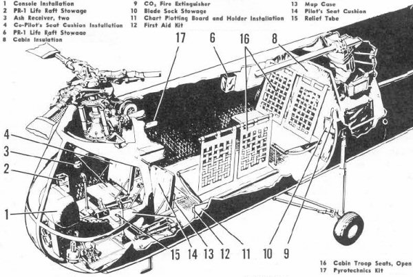
The rescue hoist was mounted above the right front seat and the rescue hatch below it so it had to be removed or folded forward for hoist operations:


There were several instrument panel arrangements. The top one was BuNo 128503-128600.


The cabin interior ended at the attachment point for the aft main landing gear strut;

The engine was mounted aft of the hole in the bottom of the fuselage and backwards, so the drive shaft pointed aft and the engine exhaust stack was forward of the engine.

The engine was mounted at an angle and drove a gearbox that had outputs forward to the front rotor and upwards to the aft rotor.

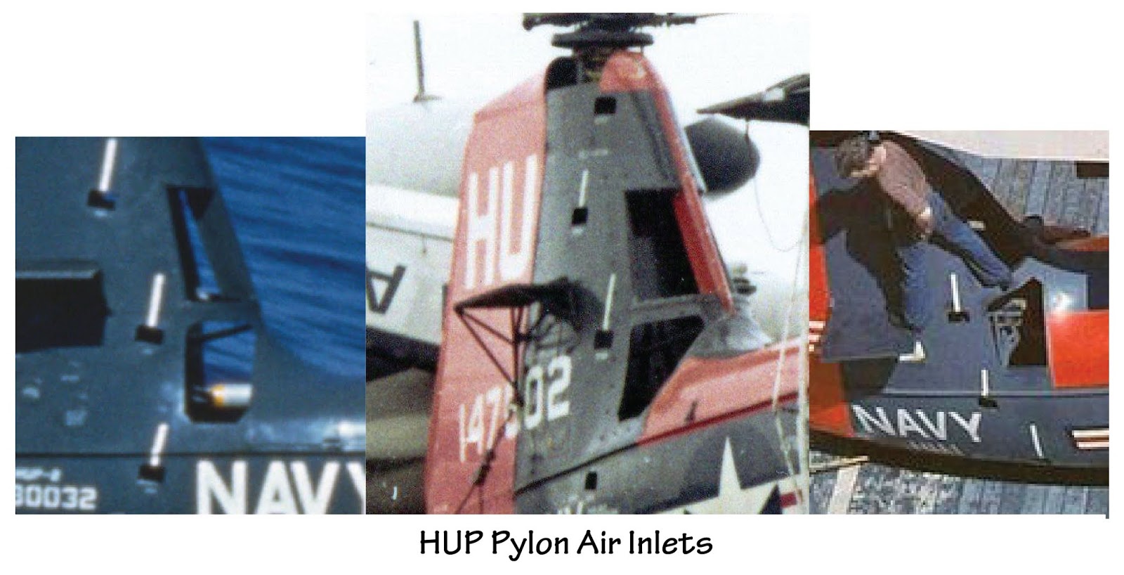
The above inboard profile was created before the second pair of air inlets was added to the leading edge of the pylon and it appears to have an early version of the trailing edge of the fin. (The second pair of air inlets was added to leading edge of the HUP's aft pylon after it first entered service in order to increase cooling air to its hard working radial engine mounted in the fuselage.) The opening looks like a rounded rectangle from the side but because of the airfoil shape of the pylon cross section and the pylon's interface with the fuselage, it looks very different when viewed from other angles.
This fuselage stations drawing can't be strictly relied on for shape but the station dimensions should be accurate (the overall length of the "shadow" on the ground was 31' 11"):

Or a bit less as shown on this three view;


The HUP-3s were H-25s built under contract to the Army. Fifty were delivered to the Navy instead. The H-25s had a slightly different interior and a different rotor head; the Navy may have installed the HUP rotor heads at some point.

Another difference was that some H-25s (51-16577 and 51-16584 and subsequent) had a fairing on the right side of the fuselage associated with the field litter installation ( seen here under the side number of HUP-3 BuNo 147602):

For an excellent in-box review of the Amodel 1/72 HUP kit, see http://alexsmodelling.blogspot.ru/2017/03/hup-retriever-amodel-kit-review.html
Gordon Hewstone built the Siga 1/72 UH-25B kit: "It's a relatively crude kit to which I added a few details such as the lights and wiring on the landing gear".

