For background on the development of the McDonnell F3H Demon from a Westinghouse J40-powered interceptor (the requirement that resulted in the XF3H) to an Allison J71-powered general-purpose fighter (ultimately, the F3H-2), see
http://tailspintopics.blogspot.com/2010/11/f3h-demon.html.
There was an intermediate step, the Westinghouse J40-powered F3H-1N, which disappointed to say the least. About half of the 60 built never even received engines, which was probably a good thing since J40 engine failures in the XF3H and F3H-1N resulted in three dead-stick landings and four crashes, two of them fatal.
Converting an F3H-2 to an F3H-1N is non-trivial but doable. The major changes are the wing planform, the one-piece windscreen, and the afterburner. (It also had the early, longer beaver tail; see the post referenced above.)
The good news is the -1N wing (dashed lines) is roughly the same as the -2's forward from a line running along the aft side of the wheel well to the trailing edge of the wingtip.
There was a small fence on the aileron instead of a chord-wise one on the wing.
(What looks like an outboard aileron is really the marking of a no-step area.)
Another view of the aileron and flap from the right side (note the fuel dump mast between the aileron and flap).
This view of the later XF3H-1 flap and aileron that were carried over to the F3H-1N shows how the forward edge of the flap extended farther forward on the lower side of the wing. (Note that the big wing fence was not carried over.)
The one-piece windscreen is probably the biggest challenge:
Since there was no flat windscreen center pane on which to project the gunsight reticule, the glass had to be included on the gunsight itself.
Illustrations of the F3H-1 cockpit indicate that the gunsight was slightly offset to the left of center.
Also note the blank panel where the radar scope was to be located. Although the F3H-1 was originally intended to have a visual-assist radar, the F3H-1Ns were delivered with an APG-30 range-only radar. (The small instrument on the blank panel is a range indicator.)
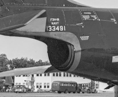
The Westinghouse J40 afterburner nozzle was a clam-shell type, with the split line vertical. The clam-shell actuators were covered by a small fairing on each side of the aft fuselage. The nozzle didn't extend as far out of the opening in the fuselage as the J71's.
Additional details are provided here: http://tailhooktopics.blogspot.com/2021/02/westinghouse-j40-afterburner-nozzle.html
This illustration provides a comparison of the F3H-1N with one completed with the -2 wing and the Allison J71 engine.
The auxiliary-air inlet on the side of the fuselage was rarely seen open. It was also present on the early F3H-2s but subsequently deactivated. The panel lines remained, however.
One of the unusual aspects of this paint scheme is that in addition to the unpainted metal (or aluminized epoxy paint) around the tailpipe, the tailboom under the stabilator appears to have been painted an off-white as was the inner half of the underside of the stabilator, while the outer half of the stabilator was blue (it looks light colored in the following picture but I think that's a reflection of the concrete).