Revised 11 March 2013
Note: I'm making progressive updates and modifications to this post. Jodie Peeler is also working up a build review of the Cyber-Hobby SH-3D, the release of which caused me to draft it. (For Jodie's build, see http://tailspintopics.blogspot.com/2013/04/cyber-hobby-sh-3d-build-by-jodie-peeler.html)
This turned out to be very confusing from a configuration standpoint. I still don't have a handle on it but here is what I have so far...
The Sikorsky SH-3 Sea King was originally designated HSS-2, a twin-turbine follow-on to the single-piston-engine powered HSS-1 and one of the U.S. Navy's more egregious past abuses of its designation system in pursuit of a new aircraft without bothering to formally initiate a development program for it.
Its primary submarine detection system capability was the dipping sonar.

In summary, the major ASW variants were:
SH-3A: Original production Sea King for the US Navy, which took delivery of about 225.
Low aspect ratio horizontal stabilizer (see picture above)
Jodie Peeler advised that: "early HSS-2/SH-3A/VH-3A airframes had two air data probes over the starboard side of the cockpit; this was later changed to the more familiar configuration with one over each side."

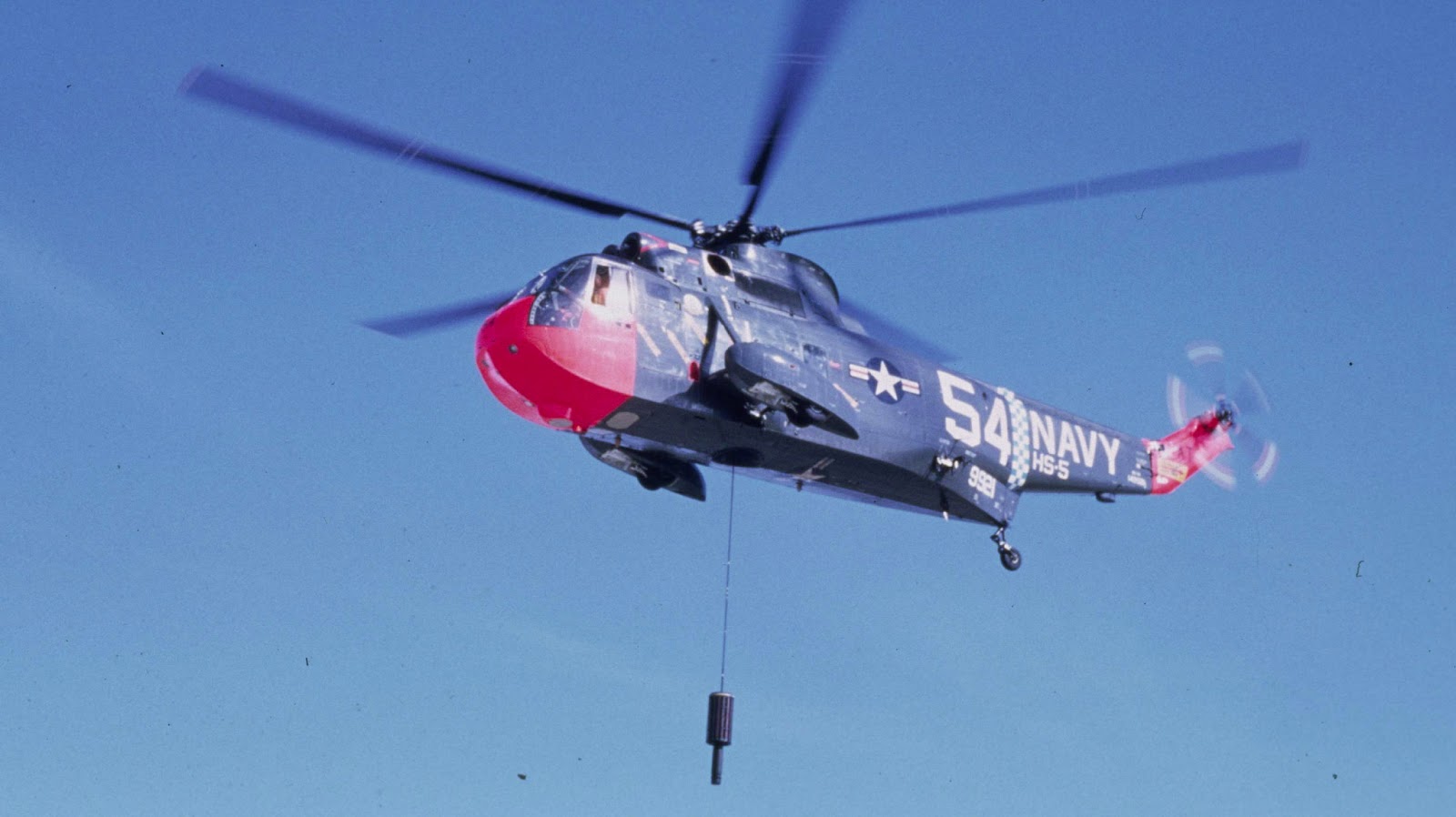
Note that flotation bags have been added to the sponson of this SH-3. If an engine failed while the SH-3 was deploying the dipping sonar, the power required to hover was almost certain to exceed the power available, resulting into a descent onto the water.The Sea King was therefore designed with a boat hull and outboard sponsons to allow a water landing. As it happened, the sponsons were not adequate to insure that the helicopter would not tip over if both engines were shut down, so inflatable floatation bags were added on the outboard side of the sponsons to provide additional stability.
The SH-3s were originally painted overall engine gray which was subsequently changed in 1968 to a light gull gray and white scheme. The colors were inverted from the airplane scheme, presumably because the nuclear flash was almost certainly to come from above and the gray might help reduce the detection range of a submarine's lookout.

Naval Aviation News March 1968
The inlet shield was added as a result of icing incidents in 1964, one of which resulted in a double flame out and crash landing. It is often referred to as a FOD shield but my impression is that it wasn't of much benefit in that regard. It did affect engine performance so it was sometimes removed when there was no prospect of icing and maximum hover performance was required.

SH-3D: Two conversions from SH-3As and 74 new production for U.S. Navy. The only major difference between the SH-3D and the -3A initially was the substitution of more powerful T58-10 engines for the -8s along with an uprated transmission to allow a higher gross weight. It also appears to have gotten a beefed-up sponson-support strut.


SH-3H: 163 conversions of existing SH-3s in lieu of new procurement
The SH-3H was a major upgrade to the Sea King ASW mission effectiveness as well as providing an anti-ship missile defense capability. To augment the dipping sonar, a towed MAD bird was added in a lengthened right-hand landing gear sponson. Sonobuoys and smoke/light markers had originally been deployed by throwing them out the cabin door; now sonobuoy dispensers were built into the floor of the aft fuselage and the left-hand sponson was lengthened to accommodate 24 smoke/light markers. Data link equipment allowed for closer coordination with other elements of the ASW defense. The additional mission of anti-ship missile defense was to be accomplished with a large search radar mounted under the fuselage, ESM equipment, and provision for carrying and controlling a chaff dispenser pod. First flight of an SH-3 modified to the H configuration was accomplished in 1972.

The H's search radar was subsequently removed to reduce its weight.

I suspect that some SH-3 pictures are misidentified as to the revision letter. The Sea King was in service for a very long time (it first flew in March 1959, production deliveries began in 1961, and the last U.S. Navy Sea King was retired 45 years later) and helicopters are relatively easy to upgrade and modify, which happened a lot in this case. Since the SH-3Hs retained their original SH-3A/D Bureau Numbers and the designation marking was relatively small, it would be easy to look at the Bureau Number and identify the aircraft as an SH-3D rather than the SH-3H that it became.
It's also not clear when some modifications were introduced or whether they were retrofitted to earlier Sea Kings without changing the suffix letter. For example, were some SH-3H features, e.g. sponson modifications, originally developed for the SH-3D? Was the added port-side cabin window on more than the SH-3H?
Another point of confusion is that an SH-3G configuration was created from SH-3As and -Ds. The dipping sonar and other equipment was removed to provide more useful load and room in the cabin for utility missions. However, the capability to reinstall the ASW mission equipment was not only not compromised, some sources suggest that it was a field-level action. For sure, some SH-3Gs were subsequently overhauled and converted to SH-3Hs. Although not a hard and fast rule, SH-3Gs were assigned to HC squadrons.

The red lines show the location of the sling-load attach points relative to the sonar well opening, the right half of which (it was removed on the SH-3G or covered) is also shown in red.

In June 1986, the first SH-3H that went through the last(?) SH-3 Service Life Extension Program (SLEP) was rolled out at Sikorsky. Among many detail changes and repair/rework were the installation of the crashworthy seats, redesigned cockpit side windows, an improved rotor head and bifilar, and the modification of the T58-10 engines to the T58-402 configuration with 100 more horsepower. These were painted in a new tactical paint scheme, "designed to reduce the IR signature and visible detection".

It's not clear when other changes were made, for example the configuration of the doghouse vent:

The ASW equipment was more or less permanently removed from some SH-3Hs as they were replaced by SH-60Fs. These were redesignated UH-60H.
So what was in the cabin? This is the sonar system installation in the SH-3A.

The SH-3H, because substantially more equipment had to be monitored and managed, had a wider crew console. (Note engine inlet shield not shown; side and top view not to the same scale; and the left sponson is only representative.)


For pictures, interior and exterior, of the SH-3H at the Quonset Air Museum, North Kingston, Rhode Island museum, see http://www.williammaloney.com/Aviation/QuonsetAirMuseum/SikorskySH3HSeaKingHelicopter/index.htm. This aircraft has crash-worthy seats installed, one of many changes over the life of the SH-3H. Although it has the cabin consoles and seats of the SH-3H, the sonar installation has been removed.
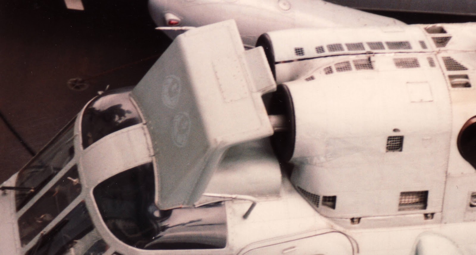
If you look closely, you'll also note that this Quonset SH-3H has an ice shield in front of the engine inlets that is clearly shaped differently from the original: the forward edge of the opening is straight rather than curved and its interior is sculptured into what amounts to a bowl, probably to minimize the horsepower loss.
The confusion and uncertainty about the configuration of the Sea King isn't helped by the fact that it was license-built by four different foreign manufacturers and operated by more than a dozen nations in addition to the U.S. Numerous detail differences resulted, including a six-bladed tail rotor, that are not present on any U.S. Navy Sea Kings.
The U.S. Navy also repurposed some SH-3s for executive transport (VH-3A/G), minesweeping (RH-3A), and combat rescue (HH-3A) with the removal of the ASW mission equipment and the addition of role-specific stuff. The U.S. Air Force and Coast Guard also bought Sea Kings, which accounts for all but one of the rest of the suffix letters. The USAF CH-3B was a Sea King stripped of ASW mission equipment for utility missions. The USAF CH-3C had a modified fuselage with the sponsons relocated for a tricycle landing gear and a rear ramp; the USAF CH-3E and HH-3E were similar to the C but with more powerful T58 engines. The Coast Guard HH-3F was the same basic configuration as the CH-3E.
And finally, two SH-3Gs were modified to be YSH-3Js that were LAMPS III avionics/mission equipment test beds for the SH-60B.


