2 September 2025: I added some detail on the auxiliary air doors.
18 November 2016: For a note on F-4K XT-595 first flight markings, see http://tailhooktopics.blogspot.com/2016/11/f-4k-first-flight-markings.html
17 November 2016: I apparently noted but forgot to add this excellent description of empennage detail differences: http://phantomphacts.blogspot.com/2014/05/differences-between-phantom-fg1-and-fgr2.html
11 October 2015: Added additional information about engine inlet change
10 October 2015: Added nose landing gear illustration of difference between J79 and Spey F-4K/FGR.1 Phantom
21 February 2014: I added a comparison of the difference between the boundary-layer-removal hole patterns on the forward variable ramp.
15 December 2013: I added some more information on the fuselage changes and the afterburner shroud.
13 December 2013: I added some information about the F-4K changes required so it fit on the elevators of the British carriers.
11 December 2013: I revised the comparison of the area aft of the afterburner nozzle to show that the absence of a "step" in the upper line of unpainted metal was on the prototypes XT595 and 596 and the first production F-4K, XT857 only. The M prototype retained the step.
Note that I refer to the Spey-powered Phantoms as the F-4K and F-4M instead of FG.1 and FGR.2 respectively, the proper British designations.
The key points are these:
1. Air inlet width increased by three inches on each side (Derek Bradshaw). Note that the original inlets were about 43" deep and each had an inlet area of 500 square inches. Widening an inlet by only three inches would increase the inlet area by about 25%, somewhat more than the reported increase of 20%.
2. Afterburner shroud outside diameter of 43 inches; diameter of shroud at aft edge, 38.5 inches (from the circumference measured by Rob as reported on Britmodeler)
3. Wider and higher "nacelles" (bulkhead comparison drawings from Craig Kaston)
3. No change in wing span: the location and width of the trailing-edge flaps did not change and their inboard edge established the width of the F-4K/M fuselage at that point (as measured, the F-4K/M fuselage was slightly wider at the trailing edge of the wing)
4. No change to fuselage aft of the arresting hook attachment except that the outer mold line of the heat-resistant shingles was lowered and extended forward to fit the Spey afterburner shroud.
5. Increase in angle of incidence of the engine installation from 5.2 degrees (J79 measured on McDonnell drawing) to 6.75 degrees (F-4K/M specification)
6. The aft Sparrows were mounted the same distance apart as in the J79-powered Phantoms but were angled at 3.75º nose up consistent with the increase in depth of the lower aft fuselage
Note: It has been reported that the F-4K/M stabilators had reduced anhedral. This is incorrect; they had the same anhedral as every other Phantom.
A common error is to assume that the lower auxiliary air doors on the F-4K/M are in the same location as on the J79-powered Phantoms; they are not. See bottom view illustration.
I've used McDonnell-generated data, three-view drawings, lines drawings, and illustrations to create the comparison shown below, using the pretty-good McDonnell Blue Angel F-4J drawing as a baseline. Unfortunately, although it otherwise adheres pretty closely to the McDonnell B/J lines drawing, it is not exactly correct with respect to the longitudinal location or size of the J79-GE-8 engine afterburner.
An excellent set of walk-around photos of F-4M (FGR.2) XV497 by Graham Platt can be found here: http://www.britmodeller.com/forums/index.php?/topic/234949864-mcdonnell-fg1-fgr2-phantom/
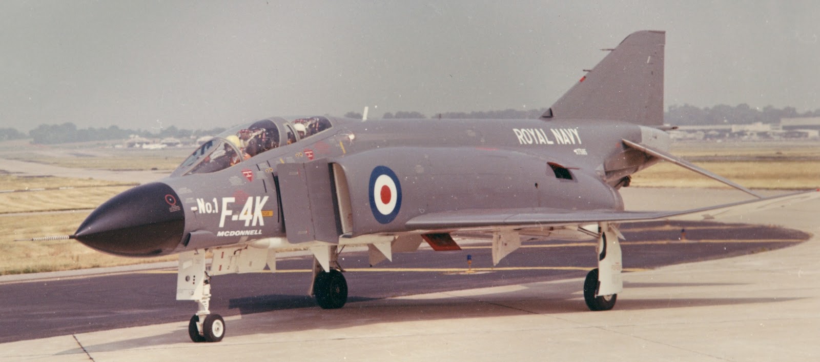
Although photos have limited use in establishing much more than basic shape or position relationships, this picture of XT-595 is as good a side view as you'll see:

The Spey was bigger around than the J79 because it was a bypass engine and had a higher mass flow. The air inlet and engine "nacelle" were enlarged accordingly, the former in width and the latter in width and height. Since the relationship of the thrust line to the location of the airplane's center of gravity is pretty important and McDonnell apparently didn't want to change the location of the arresting hook or make any significant changes to the fuselage aft of station 515 (subcontracted for the F-4K/M to Short Brothers), the Spey had to be installed at a slightly greater angle than the J79, requiring a deepening of the lower aft fuselage. (Other considerations as to engine location were the weight/cg of the Spey versus the J79 and the effect of the exhaust on the flow field around the stabilator.) Close examination of photos leads me to conclude that the top of the Spey's afterburner shroud was located at or very slightly below the top of the J79's afterburner and the inboard sides of the two engines were probably the same distance from the fuselage center line (note the weasel-wording).

The afterburner shroud moved aft to position the afterburner "petals" fully open for afterburner operation and forward when the afterburner was shutdown.
At the moment, I don't have any information on the forward and aft location of the shroud or its position when the engine was shut down. Note that XV497, the subject of Graham's walkaround referenced above, does not have the afterburner petals installed.
The red area in the following illustration corresponds to the dip in the fastener line in the next illustration.
(Fuselage station 515 is shown as A in the following pictures and "F-19" on the side view below; fuselage station 493 is B and "F18".)
Some have questioned whether there were any changes to the structure aft of FS 515. The heat-resistant shingles were different on the Spey-powered Phantoms from FS 515 to approximately FS 576. Moreover, the panel that incorporated the trough for the thermocouple wiring on the J79-powered F-4s was moved forward of FS 515 on the Spey-powered Phantoms and replaced with a titanium shingle.
Minimizing the airframe width increase at mid-fuselage due to the bigger compressor appears to have been addressed by toeing the Speys in slightly (0.55 degrees). This also had the benefit of reducing the yaw-moment arm of the higher-thrust engines, which meant that no increase in rudder control power would be required with one engine inoperative on climb out or wave off. (It also might have allowed retention of the location of the pockets for the upper fins on the aft Sparrows; the original F4H was pretty dense.)
I've somewhat refined the fuselage side view changes and added additional cross sections.
Another difference between the B/J and the K/M is the location of the lower auxiliary air doors.
Note that because of the bigger diameter of the Spey afterburners, the "wedge" just aft of the tailhook attachment point between the afterburners was not as wide since it is on the same waterline on both airplanes. This isn't a very high resolution picture, but it illustrates the change compared to the drawing above:
As it happens, my first job after college was working for McDonnell Aircraft as a junior flight test engineer on the F-4K/M Phantom program. Here is a picture of "my" airplane, YF-4K Number 1, XT-595, in June 1966, taxiing in from the first attempt by McDonnell Chief Test Pilot Joe Dobronski at first flight (the F-4K/M project pilot Bud Murray is in the aft cockpit).
I also worked with XT-596, which is now esconced in the Fleet Air Arm Museum at RNAS Yeovilton, Ilchester, Somerset, UK (
http://www.fleetairarm.com):
A fairly direct comparison of a J79-powered fuselage with the F4K/M was obtained from the Robert F. Dorr collection:
Note the additional auxiliary air door on the side of the aft fuselage and the low-pressure compressor bleed port just ahead of and below it. Both are shown in red on the side view illustration. When the aircraft was shut down, these gradually drooped to just barely open.
These doors served two purposes. At low speed and on the ground, they provided additional cooling air to the engine compartment. At very high speed, they relieved pressure in the engine compartment greater than 10 psi above ambient by opening when the pressure exceeded the ability of a door's actuator to hold it closed. The actuation of the doors was different between the J79 and Spey-powered F-4s: the former (which were only on the bottom of the fuselage) opened when the gear handle was down and at high engine compartment pressure in flight; the latter (all four) were controlled by airspeed and open below 210 knots as well as at high engine compartment pressure in flight.
Another example is this side-by-side picture taken aboard Independence in 1975:
The additional extension of the F-4K nose landing gear for launch was necessary for operation from the smaller British aircraft carrier. Note the added auxiliary torque arm or "scissors" at the bottom of the strut.
The F-4K/FGR.1 nose landing gear was also raked aft three degrees.
The F-4K/FGR.1 also featured a barricade-strap cutter located on the top and bottom of the nose just aft of the radome.
Another set of changes required for compatibility with the British carriers was a folding radome and shorter fuel vent.
The radar antenna folded with the radome.
(This is from an early McDonnell brochure so details might vary.)
The fuel vent was shorter and the outlets modified into a shallow "V".
The tail light presumably moved down to the parachute housing cover when a large antenna was added to the top of the vertical fin; I don't know when or why the vent was added.
I think the bottom line is that modifying an F-4J kit into an F-4K or F-4M model is doable but may involve more changes to the fuselage than most would want to make. Frank Mitchell is not one of those people:
http://hyperscale.com/features/2002/fgr2fm_1.htm
"Chek" brought another difference to my attention that I hadn't noticed. The hole pattern on the forward variable ramp (the holes suck off the slow-moving boundary layer air) is different between the F-4B and subsequent J79-powered Phantoms and the Spey-powered ones:
On the J-79-powered ramp, there are thin strips of holes between the larger areas of holes and the pattern of the top-most segment is very different. (There is a possibility that the top of the forward variable ramp is angled up slightly more on the Spey-powered Phantom but if so, it's impossible to verify in pictures taken from different distances at different angles with different lenses.)
The inlet ramp and inlet itself were changed as well. Because the inlet was widened by three inches, its lip was moved aft about four inches to keep the shock off the leading edge of the fixed ramp properly positioned on it at supersonic speeds. Moving the inlet lip back necessitated moving the leading edge of the variable ramp (which was hinged to the trailing edge of the fixed ramp) back about three inches for the same reason. This meant that both the fixed and variable ramps were slightly wider.
More later...