Tailhook Topics Drafts

Monday, November 10, 2025

Boeing B-52 Stratofortress Wing Dihedral


And now for something completely different but it's a rabbit hole I've explored fairly thoroughly so I thought I'd share. Thanks to Ron VanDerwarker, Rob de Bie, and Haydn Hughes for information.

The B-52 is rightly famous for the bending of its high-aspect-ratio wing in flight as well as on the ground, the amount varying considerably with aerodynamic and fuel loads.


Note that the airplane is restricted in g loading to lower numbers operationally but during initial development it was taken to at least 3.5 gs.

Some believe based on three-view drawings and pictures of the airplane on the ground that the B-52 wing has anhedral (wing angled down, also known as cathedral) rather than dihedral (wing angled up).

However, the appearance of anhedral when on the ground is deceptive, a combination of a swept wing viewed at an angle of incidence from the front (also see https://tailspintopics.blogspot.com/2014/03/anhedraldihedral-and-wing-sweep.html) exacerbated by the significant droop of the B-52's wing when fully fueled and stationary.  

This B-52D three-view drawing appears to be both Boeing-generated and accurate, although the top view has slightly greater wing span than the front view, not unusual and resulting from differential sizing of the views.
 
Based on this drawing, I’ve verified that the wing has dihedral:


The blue line is the wing's angle of incidence (6°) relative to the fuselage; the red line is along the wing leading edge. The difference between the two indicates dihedral (I don’t know what definition was used for measuring it, but it was possibly the trailing edge).
 
This Boeing illustration also depicts the dihedral present at the wing root with the scan distortion corrected with red lines:
 
Note that the clearance depicted on the Boeing three-view under the engine pods, external tank, and wing tip is dependent on fuel load in the wing and tip tank.
I’m pretty sure that “jigged" means that the three-view drawing does not show wing droop, i.e. the wing is drawn with a dihedral of 2.5°, which is possibly the case when the wing and tip tank are empty of fuel.
 
With no fuel in the wing or the tip tank, the auxiliary landing gear out on the wing tip would be well off the ground with no wing droop.

 
When generating lift, of course, the wing bent upward along its span.
 
For modelers building a B-52, there are two ways of incorporating wing bending if desired: 1) bending the wing and 2) modifying the angle of the attachment of the wing to the fuselage. The latter is incorrect and doesn't accurately represent the bending of the wing itself along its span but is an easier way of positioning the wing tip correctly with respect to the ground for a given fuel load. Nevertheless, Haydn Hughes did the former successfully: "Back in 2002 I made a couple of saw cuts in each wing of slightly different widths and inserted strips of plastic card until I got what I thought was a reasonable 'bend' in the wing. This did mean I had to replace the vortex generators though!"
 
My guess is that it would be more accurate to make the saw cuts perpendicular to the leading edge.
 
Another suggestion for bending the wing is to assemble the wing halves and then make razor cuts in the lower wing (probably best perpendicular to the leading edge and including a bit of the leading and trailing edge of the upper wing) and then gluing the gaps closed. Note that the wing outboard of the external tank will have very little if any droop. 

Monday, March 31, 2025

Ginter Books


 Steve Ginter no longer has his own website but he is still creating and publishing books. You can contact him directly for availability and pricing (nfbooks@sbcglobal.net ) or look for them here: https://daviddoylebooks.com/search?q=Ginter

Sunday, November 17, 2024

USMC F7U-3s

 The Naval Ordnance Laboratory Test Facility at Fort Lauderdale, Florida was assigned responsibility for qualification of airborne delivery of anti-ship mines. They utilized aircraft assigned to NAS Miami for drop testing. In February 1952, the air station was transferred to the Marine Corps, which inherited the test requirement. The qualification of a large, heavy mine intended for 500-kt delivery from 500 feet by the Navy's big new jet-powered patrol plane, the Martin P6M Seamaster, required a much bigger, faster jet than an aircraft in the USMC inventory, so Miami was assigned three F7U-3s over time.

The first, BuNo 128466, was one of the first sixteen F7U-3s that were powered by non-afterburning J-35 engines. It had become excess to Vought and Navy test requirements. It arrived on 30 August 1954.


It's availability proved disappointing due to a lack of spare parts among other things so it was retired in favor of a J46-powered F7U-3, BuNo 129582, which arrived on 21 July 1955..


It was stricken on 1 July 1957, probably in lieu of a required overhaul, and replaced by BuNo 129602 that was fresh out of overhaul (unfortunately, Al Casby has been unable to acquire a picture of this F7U-3 in USMC Miami markings). When no longer required for testing a year later, it was ferried for storage at NAF Litchfield Park.

Early F7U-3 Forward Fuselage

 The first 16 F7U-3s were powered by nonafterburning Allison J35 engines because the Westinghouse afterburning J46 engines were not yet flight qualified. One was modified before first its first flight to have the over-the-nose visibility increased for carrier landings. As a result, the radome, canopy, and engine inlet/tailpipe were very different.


The vertical fin was also modified during development to provide more deck clearance for takeoff and landing:

The Allison-powered F7U-3s had different inlets and tail pipes because of the greater mass flow requirement for maximum thrust and the lack of an afterburner.

Inlet without boundary layer splitter:

Simple tailpipe:


Friday, March 8, 2024

FS 12197 International Orange

 FS 12197, International Orange, has been used on U.S. Navy aircraft for high-visibility markings. It can be confused with other colors also used for that purpose. Also note that it is more red-orange than orange...


For example, Robert Thomas, a volunteer at the National Naval Aviation Museum in Pensacola, provided this synopsis:

"For the high visibility markings the USN originally used the Orange Yellow color (think the SNJ, etc.). In the early 1950s they started using International Orange on some aircraft. The Naval Air Training Command in 1952 tested various colors in hopes of better visibility. In September 1952 "Day-Glo" paint had been developed. It was labor intensive, as it had to be applied over a White lacquer finish, needed two coats, and started dulling after one to two months. After trying other paint designs, they went back to the Orange Yellow overall markings. In 1953 the USN discontinued all use of Day-Glo paint.

In 1956 International Orange paint began to be used on tactical aircraft in the continental U.S. due to the increased chance of air-to-air collisions with civilian aircraft. In 1958 Fluorescent Red Orange replaced International Orange as the standard high-visibility paint on non-training aircraft. 
In 1959 the Training Command went completely to an International Orange and White paint scheme.

In May 1964 the Navy discontinued use of fluorescent Red Orange. It also required high upkeep due to fading issues. At that point all high-visibility paint markings were to be in International Orange only, which is still used today on training a/c and where necessary on other types.
The FS numbers appear to not have changed over the years. International Orange is FS12197 and Fluorescent Red Orange is FS28913. Orange Yellow is FS13538."

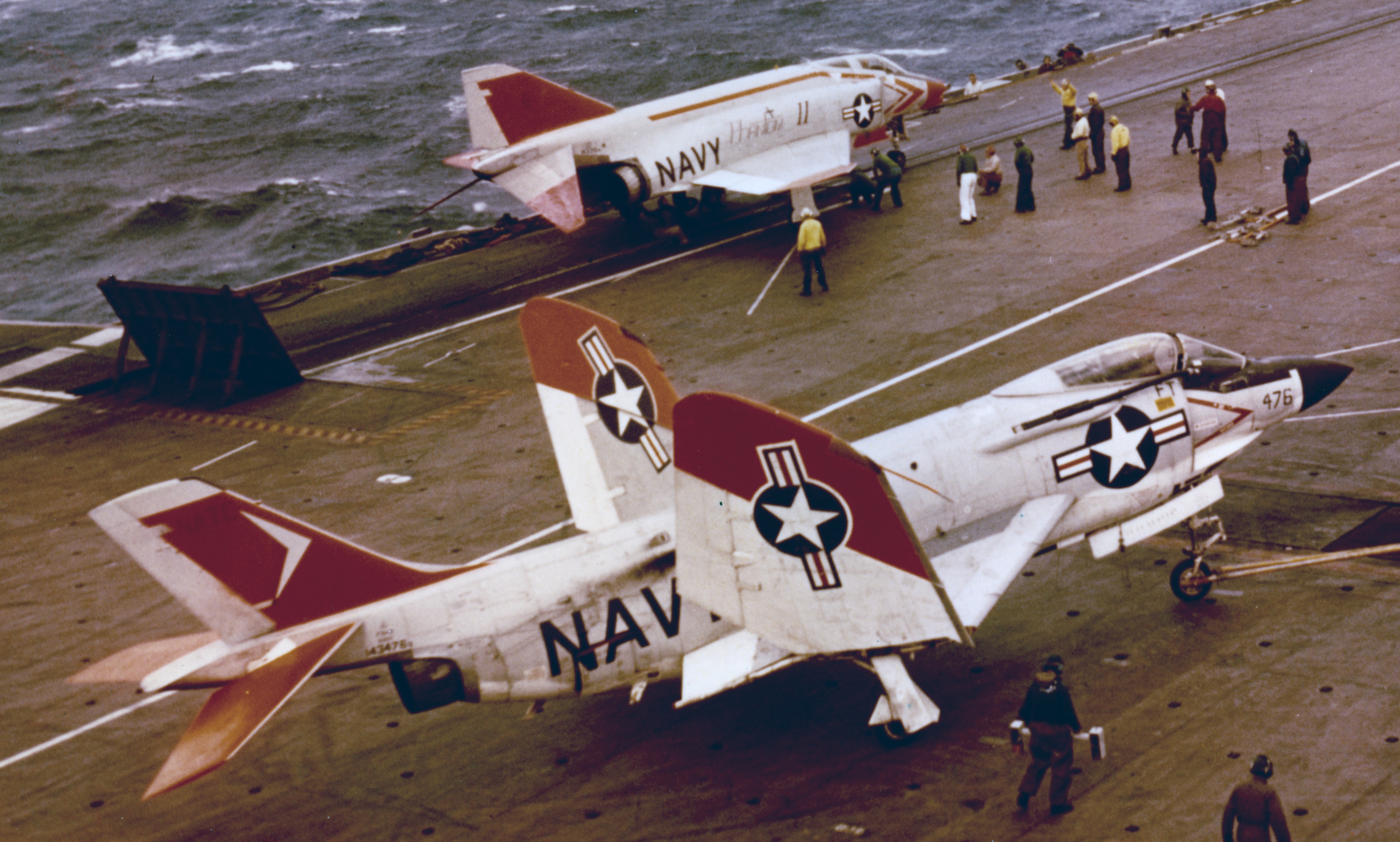
A color in a published illustration or on a computer screen is not always rendered accurately so even the color above is not necessarily true. It may not even appear to be consistent in the same picture: 

Note that the color on the top of the left wing appears to be more orange than the bottom of the left wing or vertical fin (which both appear to be more red than the sample above) and the horizontal stabilizers appear to be somewhere in between.

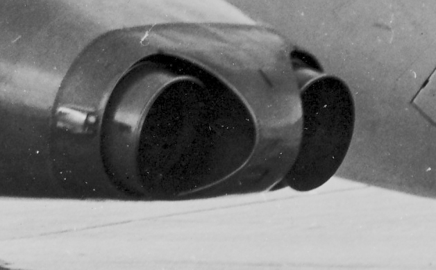
Even a direct comparison with insignia red in a pretty good photo isn't necessarily helpful:

 Of course, the underlying prime coat or adjacent color to the International Orange may affect its appearance:


Available 12197 paints also vary in color. Paul Boyer recommends Testor Model Master “Chevy Engine Red” (if you can find it) especially under artificial light; in his opinion, Testor Model Master “International Orange (FS12197)" was too dull in artificial light. Others have found Model Master Acrylic 4682 and XtraColour X104 to be too orange.

Other recommendations found on line:

https://www.cybermodeler.com/color/fs_table.shtml

 https://www.scalemates.com/colors/hataka-hobby-red-line--997/a062-international-orange-fs12197-ana-508-acrylic-gloss--9859

 https://www.truenorthpaints.com/paintstore/international-orange (looks too orange on my screen)

https://www.arizonahobbies.com/US-Air-Force-INTERNATIONAL-ORANGE-FS-12197-2-oz-bottle_p_4600.html (looks good on my screen)

 Rustoleum "Allis Chalmers Orange”

And probably as good as any, "red with some yellow added".


Tuesday, July 4, 2023

Grumman S2F Bomb Bay

 From Grumman Archives:


Friday, June 30, 2023

A-6A versus A-6E Inboard Wing Fence Locations

 1 July 2023: It turns out that there is the same drafting error on two different Grumman drawings with respect to the location of the inboard end of the leading edge slat. I've corrected it.

A question arose about the the location of the inboard end of the wing slat on the A-6A versus the A-6E with the inboard wing leading edge ECM antennas. The answer is that it was not changed. Note however, that the inboard wing fence location did change: it was moved inboard of the inboard pylon.

All dimensions shown are "wing stations" measured from the fuselage centerline.

For more on the major configuration differences between the A-6A and A-6E, click here: https://tailspintopics.blogspot.com/2015/09/grumman-6a-vs-6e-intruder.html