

For a summary of the McDonnell F3H Demon program, click here: https://tailspintopics.blogspot.com/2010/11/f3h-demon.html
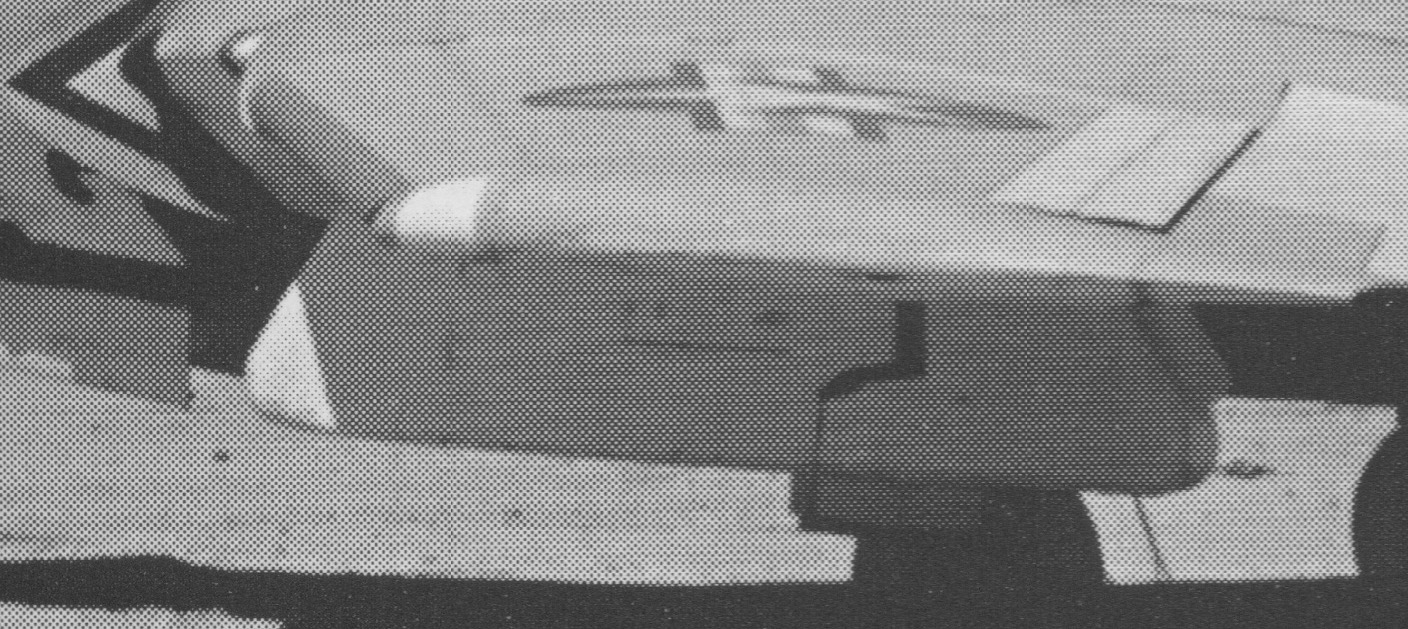
Among a few early changes to the F3H Demon that were required after it first entered service were roll-control spoilers. These were literally scabbed onto the top of the inboard surface of the wing ahead of the flaps. Two long "fingers" were present to cover the openings cut into the wing skin for the actuators. Note that while the spoilers look like speed brakes, they were never extended in flight at the same time.

Don Hinton Photo
These were belatedly required because a notable loss of roll control power was being experienced at high indicated air speeds. The reason was a lack of wing torsional stiffness. At a high enough speed, the aileron, instead of reducing or increasing lift on a wing, began to function like a servo tab on a control surface, in this case twisting the wing so that instead of increasing lift, the deflected aileron caused the wing to deform, reducing its angle of attack and therefore lift (the Wright brothers actually used wing warping initially for roll control instead of ailerons).
As it happened, in the process of redesigning the F3H to substitute the Allison J71 engine for the Westinghouse J40, McDonnell also increased the wing area aft of the wing torque box.

Presumably this reduced the wing's torsional stiffness but it was not predicted to be enough to be a problem at high speed.
Instead of beefing up the wing to increase torsional stiffness, McDonnell and the Navy elected to add inboard spoilers. When the airspeed increased above 560 +/- 7 knots, lateral control was switched from the ailerons to the spoilers; when the speed subsequently decreased below 545 +/- 7 knots, lateral control switched back (the switch took about two seconds). When flight control was via the spoilers, only one was extended at at time; the ailerons were fixed in a neutral/faired position.
The need for this complication was fairly limited, since the F3H could only achieve this indicated airspeed in level flight below 10,000 feet and only in a dive below 20,000 feet. However, it was considered by the Navy to be essential and in fact the switchover speed was classified, presumably because knowledge of it and the switching delay might prove useful to an opponent in air-to-air combat.
When I observed in a blog post that both spoilers shouldn't have been extended on the F3H at the National Naval Aviation Museum, someone wrote to suggest that they sometimes were. Well, maybe, but until I saw a video recently of an F3H taxiing with the wings folded and both spoilers extended, I was dubious:

Jerry Wells supplied the answer from F3H maintenance manual documents. It turns out that the push rods and bell cranks of the F3H's lateral control system go from the pilot's stick out across the wing fold near the wing leading edge to actuate the ailerons and then back across the wing fold near the wing trailing edge to actuate the spoilers.

When the F3H's wings were folded and the hydraulic system was pressurized, either by a hydraulic cart or the engine-driven hydraulic pump, the complex hidden details and inner workings of the lateral control system resulted in both spoilers extending. When the wings were unfolded, the spoilers retracted. When hydraulic pressure was removed when the wings were folded, the spoilers slowly settled back onto the surface of the wing.

Note that 104's spoiler is up; 103's is not (one F3H oddity is that the pilot did not have control over wing folding; a deck crewman had to fold or unfold the wings).
Transitioning a mechanical control system across the wing-fold joint was always an interesting design problem. See https://thanlont.blogspot.com/2011/03/grumman-sto-wing-redux.html. It often resulted in ailerons being positioned "unnaturally":

It's not clear how long it took for the spoiler to lie back down after engine shutdown. In the following picture of what appears to be a respot of the deck immediately after a recovery, the spoilers on the F3H in the foreground appear to be down while at least one on the F3H coming behind it is still up.

With respect to a parked F3H, while you can be pretty confident that the spoilers are down (for sure if the wings are not folded) and the speed brakes extended (although there are exceptions), the configuration of the other control surfaces is not certain either. This photo illustrates some of the possibilities:

In most pictures, the ailerons on a folded F3H are both positioned slightly "up"; in this case—and there are other examples—they are slightly "down". It's unusual to see the flaps down and in this case, only one is. It is only rare to see an F3H parked, unfolded, with the wing slats extended and even rarer to see one with the ailerons drooping.
Among the more obvious modifications to the F-4Js flown by the Blue Angels, there were some necessary for operation into civil airports world wide. These included the addition of the anti-lock braking system (standard on USAF F-4s, not on Navy ones), a gaseous-oxygen system (not all the venues would have the capability to fill the liquid-oxygen system), a "special" drag chute*, and additional radios (VHF nav/com and ADF for example).
* Rarely seen but then unforgettable
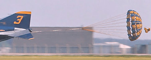
Thanks to Peter Greengrass' Google-fu
The most obvious of these modifications from a modeling standpoint was an antenna array in the rear canopy. I'm still in need of its exact description and function but I'm pretty sure that it was associated with low frequency direction finding. Beginning in the 1920s, a pilot could determine where a known radio station was relative to his airplane with a direction-finding radio and display; that allowed him or her to navigate to a destination and make an approach for landing on the darkest night or in low visibility conditions (since needle was just as happy to point the way to the lightning in a thunderstorm as a radio station it also had some usefulness for avoiding one that predated radar).
There appears to be more than one antenna mounted in the rear canopy by means of a large translucent shield attached to two grey fittings on each side of the canopy:

Note the embedded wiring in the shield and the rectangular antenna located at its aft end. It's not obvious in the picture above but there are large openings in the shield on its top and on each side:

The color of the rectangular antenna varies in different photographs from a dull fiberglass appearance to reddish.
A view from each side to size the shield in lieu of a drawing :

Note that photographs are once again not to be relied on for determination of actual color (for my summary of the Blue Angels color scheme over the years, see https://tailspintopics.blogspot.com/2011/04/blue-angel-blue-and-gold-draft.html
For more on the configuration of F-4Js flown by the Blue Angels, see https://thanlont.blogspot.com/2017/05/the-short-tragic-operation-of-f-4.html
Thanks to Peter Greengrass for providing fairly high resolution pictures that could be cropped to show this feature.
My understanding is that the Thunderbird's F-4Es had a similar if not identical antenna farm in their rear canopies. Photos of it or better photos/illustrations of the Blue Angel's would be appreciated.

From Baugher (http://www.joebaugher.com/usattack/newa6_4.html):
The KA-6D was a tanker version of the Intruder, created by conversion of existing Intruder airframes.
Grumman had tried out a buddy midair refueling pod underneath a conventional A-6A (BuNo 147865). In addition, Grumman fitted an internal refueling package into BuNo 149937. But these projects never proceeded any further because of a lack of any perceived need for a tanker Intruder.
However, in 1968 the Navy changed its mind and Grumman was finally given authority to proceed with a tanker version, designated KA-6D. The first KA-6D was obtained by modifying BuNo 151582. It first flew on April 16, 1970, crewed by Chuck Sewell and D. R. Cooke..
The KA-6D was fitted with an internal hose-and-reel refueling package, with the drogue fairing protruding from underneath the rear fuselage. It could also carry a D-704 refueling pod on the fuselage centerline. The D-704 acted as a backup to the internal refueling system, and provided its own power via a ram air turbine mounted on the front. The radar and most of the DIANE equipment was removed, but the KA-6D still retained a visual bombing capability (which was seldom exercised). There were only minimal controls provided for the second crew member, whose duties were now navigation and the monitoring of the refueling operation.
A total of 90 KA-6Ds were produced by modifying existing Intruder airframes. Although all of the planes used airframes that were originally built as A-6As, 12 of them had previously been upgraded to A-6E standards. When rebuilt from A-6As, the KA-6Ds received all new fuel tanks, with two fuselage bulkheads being replaced. There was extensive rework of the outer wing panels. The aircraft was completely rewired. The Omega global inertial navigation system was fitted, with the entire suite being controlled by an ASN-41 navigational computer. For typical missions, the KA-6D caries four fuel tanks on the wing pylons. The D-704 is sometimes carried as a backup to the primary hose-drum unit, or as a means of ferrying the pod to other units.
The first deployable Intruder squadron to receive the KA-6D was VA-176, which received its first tankers on September 25, 1970. Each deployed Intruder squadron typically had 3 or 4 KA-6Ds assigned to it for the tanker mission.
There was always the ever-present danger that the refuelling hose could become stuck in the deployed position after a refuelling operation and could not be reeled in. While the refueling hose is deployed, the carrier arrester hook could not be extended and it would be impossible to land on a carrier. The unfortunate aircraft would have to find a land base very quickly or the crew would have to eject. In order to prevent this from happening, there was an emergency explosive cutter which severed the hose and allowed it to drop into the sea.
From the KA-6D Flight Manual
Inboard Profile

Pilot's Side of the Cockpit
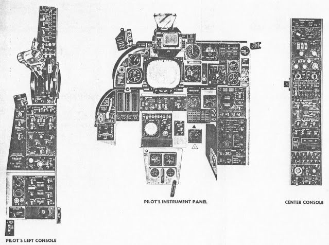
Observer's Side of the Cockpit

For more on the D-704 store, see https://tailspintopics.blogspot.com/2015/06/things-under-wings-inflight-refueling.html
16 September 2021: Bill Spidle spotted the faint lines of the TBF oil cooler duct that I missed on the powerplant installation illustration.
First, note the different cowls of the TBF-1 and TBM-3:

In both instances, the upper air inlet only provided air to a downdraft carburetor aft of the engine. Another inlet was added to the bottom of the cowl on the TBM-3 to provide air directly to a single oil cooler mounted at the bottom of the engine nacelle. After passing through it, the air exhausts out the bottom of the cowling through a flap similar to a cowl flap.
The TBF-1 had two oil coolers, one on each side, exhausting through doors on each side of the forward fuselage.

There appears to be a duct in the engine compartment leading to the oil cooler with its forward end behind the aft row of engine cylinders:

You have to look closely to see the lines representing the duct leading to the oil cooler (item 150) and its forward opening in this illustration:

Note that it is routed above the hot exhaust collector (item 149).

However, it does seem like a poor way to provide air to the oil cooler, given that it's being taken from a hot engine compartment, but there doesn't seem to be any room between the cylinder heads and the side of the cowling for the duct to extend forward.
And perhaps that's why the TBM-3 powerplant installation was revised to provide an air inlet at the bottom of the cowl:

That relocation resulted in a change to the cowl flap configuration (those provide the exit for air in the engine compartment at low speeds and high power settings to increase the air flow over the hot engine cylinders).
This inboard profile adds to any confusion:
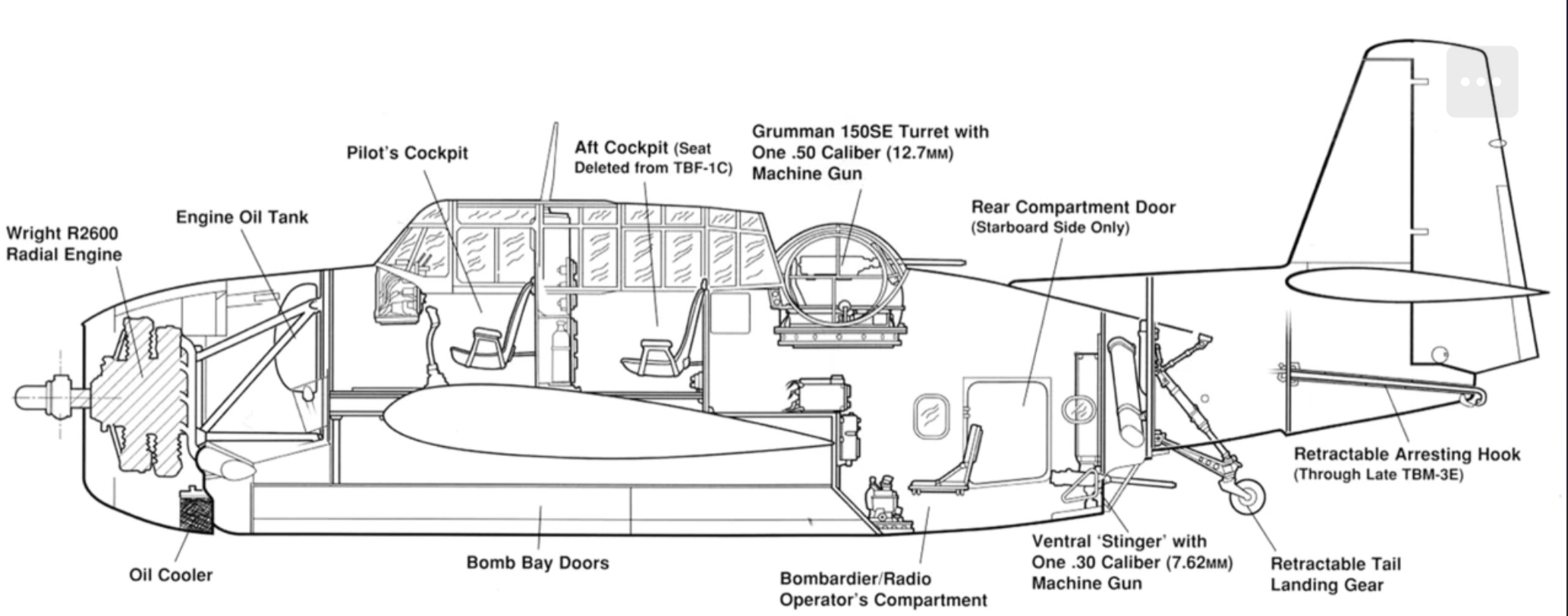
14 August 2021: Jerry Wells provided me with maintenance manual details that required a slight revision to the drawing
9 August 2021: I should have checked with Boom Powell before I posted this...

For night photography, the RA-5C could be fitted with a self-powered flasher pod, part of the LS-43AI "Flasher System Photographic, Aircraft".

From Vigilante!

I created this drawing from odds and ends of documentation as well as photographs not well suited to the task but I think it will be adequate as a modeling reference (note: Rev A corrects the shape of the small cooling air inlet at the front of the pod; Rev B corrects the aft end of the pylon where it attaches to the wing). Unlike other air-driven ECM/IFR pods, the generator was turned by a propeller with only two blades.

The pod could be mounted under either wing:

This picture should suffice for a cross section:

ReccePhreak asked about the F9F-8P's photoflash pod needed for night aerial photography. The answer turned out to be hidden in plain sight and it wasn't a pod but more of a pylon. It isn't identified on the F9F-8P SAC three-view but it's there at Wing Station 96, 25 inches outboard of the pylon used for external tanks and just outboard of the wing fence:

I also found two pictures of it on the wing in Steve Ginter's Naval Fighters Number Sixty-Seven, Grumman F9F-6P/8P Photo-Cougar:

And another, not mounted, in my files:

Note that it's about twice the width and depth of the inboard pylon. Jerry Wells then provided me with technical manual information for the F9F-8P and F2H-2P that included a description of the two different flash-cartridge holders and this isometric cutaway illustration of the F9F-8P Mk 51 Mod 14 pylon.


The F2H-2P did utilize a pod that incorporated the A-6 and B-4 cartridge holders for night photography.


This is my notional illustration of that pod.

One point of confusion is that the F2H technical manual was explicit about a pod with the B-4 ejector being loaded on station 7 only but the 20-cartridge pod in the picture above my drawing is mounted on Station 2 (the eight pylons are numbered from left to right).
Note that the pod in both pictures appears to be mounted on the outboard F2H pylon (station 1/8) that was located farther forward than the next one inboard but that's because a fairing was added on the front of the AERO 14 pylon at station 2/7 to cover the wiring added to control the flash cartridge deployment.


