Monday, May 20, 2013

Trumpeter 1/48 A3D-2 Skywarrior

This is a work in progress as I come across ilustrations that help resolve issues with the kit. It is based in part on pictures provided here: http://www.1999.co.jp/eng/10207663

24 April 2025: For TA-3B, see: https://tailspintopics.blogspot.com/2013/09/ta-3b-skywarrior.html

Also wing pylons: https://tailspintopics.blogspot.com/2013/10/a3d-skywarrior-external-pylons.html  

Location of main gear wheel wells: https://tailhooktopics.blogspot.com/2018/05/eka-3b-aft-fuselage.html

Vertical fin fold: https://tailhooktopics.blogspot.com/2014/02/a3da-3-skywarrior-vertical-fin-fold.html

A3D-1Q:  https://tailhooktopics.blogspot.com/2013/06/a3d-1q-notes.html

4 April 2014: For an error in the length of the bomb bay doors, see http://tailspintopics.blogspot.com/2014/04/trumpeter-148-3-skywarrior.html

26 May 2013: I've added a picture of the tailhook area, one from the rear of the engine, and a better one of the tail turret.

22 May 2013: I've added an illustration of the gun turret and revised the JATO installation drawing

21 May 2013: I've added discussion and illustrations on the tailhook

And an illustration on the JATO provisions...

The Trumpeter 1/48 A3D-2 Skywarrior kit is very impressive but contains a few blunders that arise in part from the many variations both between variants (Bombers and Versions) and over time.

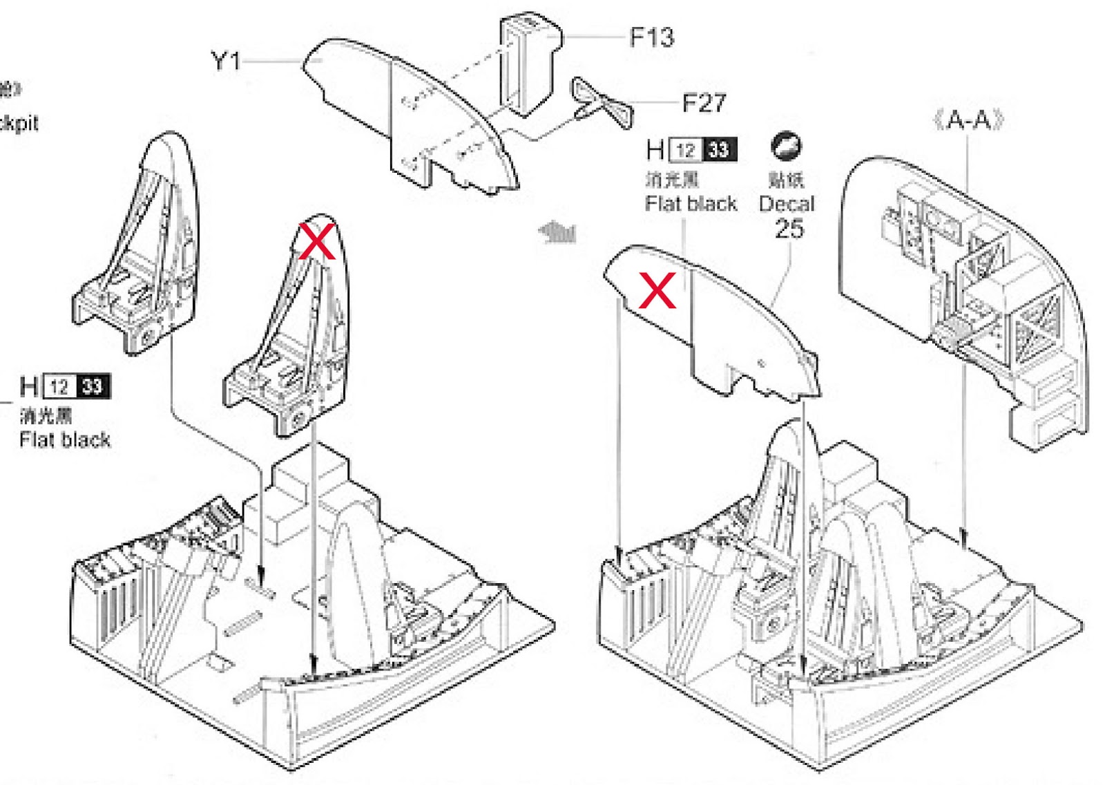
The cockpit is very detailed but there are a couple of items to address.

The most notable and probably just visible is the pilot's seat, primarily the headrest. The seat does not have an integral headrest; instead, its headrest is mounted on the back of the headrest of the rearward-facing seat. The seat is also slightly different in shape from the bombardier's and the rearward-facing seat.
A less important but more easily fixed error is that the instrument panel, per se, does not extend past the right side of the center console.

The kit, however, provides only the basics of the bombardier's station but the configuration did vary over time. The aft bulkhead (which was the forward end of the forward fuel tank) was bulged out, not flat, and the detail is for a later configuration than an early Bomber.

This is a mid-life configuration that is similar to the picture above and more appropriate to the Bomber represented by the kit; the asterisks denote removals and modifications of KA-3B equipment.
What is provided in the kit at the bombardier's station appears to be the configuration in the late KA-3B configuration.

The lower entry/escape hatch is in the Bomber location but is the thicker Version configuration. It should look like this:
Also see http://tailspintopics.blogspot.com/2013/05/trumpeter-148-a3d-forward-fuselage.html for this and a few other forward-fuselage details.

The kit wing has the original airfoil but the slats that were incorporated on the wing with the cambered leading edge airfoil. See http://tailspintopics.blogspot.com/2010/09/mighty-skywarrior.html for a discussion of this and an explanation of the basic differences between Bombers and Versions. The airplane that the kit represents should have the original wing.

For some reason, kit manufacturers seem to have difficulty with tailhooks and this kit is no exception. However, the hook is both hard to see when stowed and seldom seen deployed so there are mitigating circumstances. The kit hook resembles a shepherd's crook.
The actual hook looks like this in profile:
And this from is a picture from the side and above:
Aerofax Collection
And the tailhook installation from below
Note the recess that provides clearance between the fuselage and the hook in an off-center engagement and the black "bumpers" that protect the skin aft of the recess.

The hook point is notably wider than the shaft proper and resembles a horse's hoof:
It will have a groove at the throat to hold the arresting cable like this AJ Savage tailhook:

Antennas: the instructions would have you put on antennas that don't belong on a Bomber with this particular nose:

The main landing gear wheel wells are incorrect but probably too much trouble to correct.
For more on this and the difference in brakes between the Bombers and the Variants, see http://tailspintopics.blogspot.com/2013/05/douglas-a3d-skywarrior-main-landing.html

As noted in the A3D Forward Fuselage post referenced above, the fairing for the inflight refueling probe should not extend aft as far as it does. However, the Bomber represented by the kit might very well have not had the inflight refueling probe installed.

In the picture above, you can see some tiny rectangles between the national insignia and "NAVY" on the fuselage. Those were the doors over the JATO bottle thrust and stabilizing hooks. (The original requirement included a deck launch option, in the event that the catapults were down, with the aid of 12 4,500-lb thrust JATO bottles.)
 These JATO attachment provisions appear to be missing from the kit fuselage.

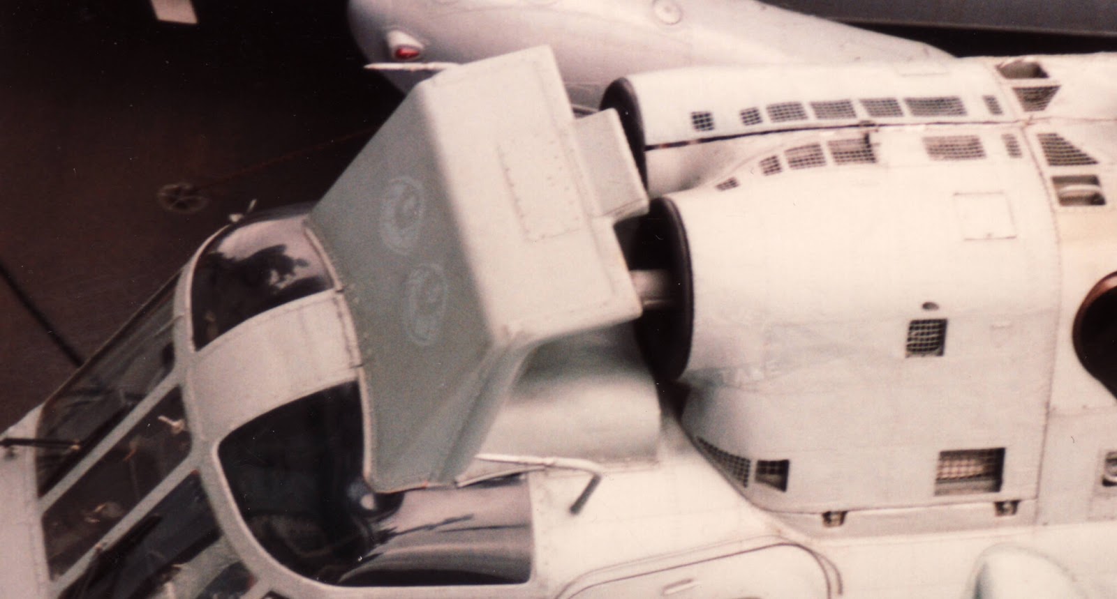
Another missing detail is the prominent shell/link slots in the tail turret ball. (There are some openings in the unseen forward end of the ball in the kit - I'm not sure what that is about...)


I mentioned that the A3D engine pylon and the fairing over the tailpipe are not symmetrical here: https://tailspintopics.blogspot.com/2013/08/a3d-3-flap-to-pylon-fairing.html. I don't know whether the Trumpeter kit is correct or not, but the degree of difference between the inboard and outboard sides is notable.
The pylon is shaped like an airfoil on its side with the top facing outboard. My guess is that this "stiffened" the pylon/nacelle installation by forcing it to one side in flight, minimizing any tendency for it to wobble laterally. It might have also stiffened the wing.

More later...


Tuesday, March 26, 2013

Spey-Powered Phantom Changes Post Updated

It would appear that several people have been looking for an update to the draft Spey-Powered Phantom post based on a comment I made recently elsewhere; I finally got around to doing it. See: http://tailhooktopics.blogspot.com/2012/05/spey-powered-phantom-changes.html

3 April update:  The 2 April update had an error in the location of the lower auxiliary air doors that has now been fixed on the bottom view drawing.

Tuesday, March 19, 2013

Vought F8U-1T Twosader

This is another draft of a subject that I am interested in but for which I lack some facts or confirmation of details.
With the acquiescence if not the encouragement of the Navy, Vought modified the F8U-2NE prototype to a two-seat configuration, its Model 408. It was Bureau Number 143710, which had originally been the 77th F8U-1. The two seater was designated F8U-1T but it more closely resembled the F8U-2NE externally with its radome, ventral fins and afterburner scoops. Although a J57-P-20 engine was installed, it was reportedly derated to produce the same thrust as the J57-P-4A engine, which presumably justified the -1 suffix.

Contrary to most published articles, the second seat was added without stretching the airframe, which avoided a cg problem. Instead, equipment was relocated and two 20-mm cannon, their ammunition, and the ventral rocket pack were deleted. The aft seat was raised by 15 inches above the front seat, providing both visibility forward and replacing some of the reduction in fuselage volume. (It was also necessary to do so in order to retain the existing intake trunking that led back to the engine.) Both cockpits were covered by one long canopy that was hinged at the rear like the single-seat Crusader’s. A parabrake installation was added at the base of the vertical fin to reduce the landing distance.

In line with its intended purpose as an advanced trainer, it retained the Sidewinder missile capability and the two cannon. (The right cannons were reportedly the two removed but I can’t confirm this.) The first flight of the prototype F8U-1T was accomplished on 6 February 1962. It was subsequently redesignated TF-8A in November in accordance with the DoD aircraft designation system consolidation.

The Navy accomplished an extensive evaluation of the TF-8A including at-sea trials.

The Twosader was also evaluated by VT-22 with student pilots. Four reportedly received training in the TF-8A. One became the first (and probably only) 1,000-mph student pilot. The Navy placed an initial order for 12 F8U-1Ts (BuNos 145648-145659) with Vought but subsequently canceled the contract because of budget priorities. None of the other countries to which it was proposed elected to buy it either (according to Bill Spidel, France, whose Navy was operating F8Us, had some on order for a time). The one and only TF-8A was eventually assigned to the Navy Test Pilot School for several years.

At some point, it was designated NTF-8A, probably because the Navy had some TF-8As that were simply F-8As assigned to the training command. This has lead to some confusion with at least one F8U flown or modified by NASA. The NTF-8A was assigned to NASA but only briefly in 1977 after the Test Pilot school retired it. It may not have even been flown there since it was bailed to Vought in late 1977 to provide training for Philippine Air Force pilots.

It crashed on 28 July 1978 following an engine failure during a training flight from Vought’s facility at Grand Prairie, Texas. The Vought instructor and the Philippine Air Force student ejected safely. According to Bill Spidel, the "rear compressor rotor tie-rod nut cover" failed.

A Vought Public Relations multi-view drawing of the Crusader includes the F8U-1T. However, the canopy clearly appears to be a sketch and too large, both in depth and length. I’ve modified it based on photographs, etc.  but can’t be sure that it is much more than better.

Monday, February 18, 2013

US Navy ASW SH-3 Sea King Variations

Jodie added some more information about the early SH-3A configuration here: https://tailspintopics.blogspot.com/2013/08/early-sh-3-configuration-by-jodie-peeler.html

Revised 24 March 2013 to add an annotated picture of the SH-3G sling load rigging

Revised 11 March 2013
Note: I'm making progressive updates and modifications to this post. Jodie Peeler is also working up a build review of the Cyber-Hobby SH-3D, the release of which caused me to draft it. (For Jodie's build, see http://tailspintopics.blogspot.com/2013/04/cyber-hobby-sh-3d-build-by-jodie-peeler.html)

This turned out to be very confusing from a configuration standpoint. I still don't have a handle on it but here is what I have so far...

The Sikorsky SH-3 Sea King was originally designated HSS-2, a twin-turbine follow-on to the single-piston-engine powered HSS-1 and one of the U.S. Navy's more egregious past abuses of its designation system in pursuit of a new aircraft without bothering to formally initiate a development program for it.

Its primary submarine detection system capability was the dipping sonar.


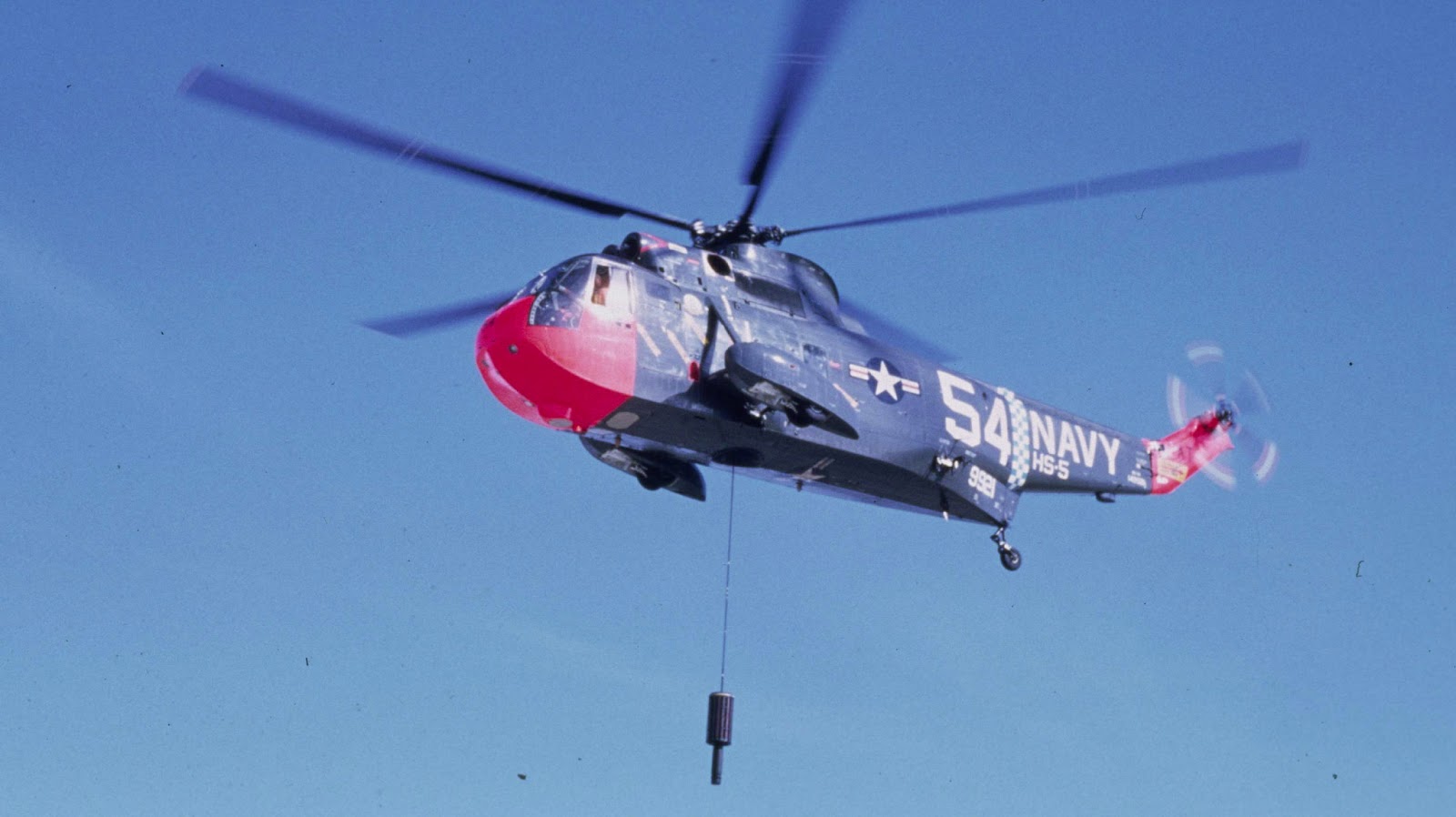
Note: this SH-3A has a radar housing on the belly that was not installed on the early SH-3As.

In summary, the major ASW variants were:

SH-3A: Original production Sea King for the US Navy, which took delivery of about 225.
 Low aspect ratio horizontal stabilizer (see picture above)
Note that this early Sea King does not have the inlet shield in front of the engines or the flotation bags on the sponsons.

Jodie Peeler advised that: "early HSS-2/SH-3A/VH-3A airframes had two air data probes over the starboard side of the cockpit; this was later changed to the more familiar configuration with one over each side."

Note that flotation bags have been added to the sponson of this SH-3. If an engine failed while the SH-3 was deploying the dipping sonar, the power required to hover was almost certain to exceed the power available, resulting into a descent onto the water.The Sea King was therefore designed with a boat hull and outboard sponsons to allow a water landing. As it happened, the sponsons were not adequate to insure that the helicopter would not tip over if both engines were shut down, so inflatable floatation bags were added on the outboard side of the sponsons to provide additional stability.

The SH-3s were originally painted overall engine gray which was subsequently changed in 1968 to a light gull gray and white scheme. The colors were inverted from the airplane scheme, presumably because the nuclear flash was almost certainly to come from above and the gray might help reduce the detection range of a submarine's lookout.
Naval Aviation News March 1968

The inlet shield was added as a result of icing incidents in 1964, one of which resulted in a double flame out and crash landing. It is often referred to as a FOD shield but my impression is that it wasn't of much benefit in that regard. It did affect engine performance so it was sometimes removed when there was no prospect of icing and maximum hover performance was required.

SH-3D: Two conversions from SH-3As and 74 new production for U.S. Navy. The only major difference between the SH-3D and the -3A initially was the substitution of more powerful T58-10 engines for the -8s along with an uprated transmission to allow a higher gross weight. It also appears to have gotten a beefed-up sponson-support strut.

It's not clear to me when other changes were made like the original stabilizer being replaced with a high-aspect-ratio one supported with an external strut. It wasn't on the SH-3D originally.

At some point, the SH-3 also received a tail rotor of slightly greater diameter than the original 10 feet.

SH-3H: 163 conversions of existing SH-3s in lieu of new procurement

The SH-3H was a major upgrade to the Sea King ASW mission effectiveness as well as providing an anti-ship missile defense capability. To augment the dipping sonar, a towed MAD bird was added in a lengthened right-hand landing gear sponson.  Sonobuoys and smoke/light markers had originally been deployed by throwing them out the cabin door; now sonobuoy dispensers were built into the floor of the aft fuselage and the left-hand sponson was lengthened to accommodate 24 smoke/light markers. Data link equipment allowed for closer coordination with other elements of the ASW defense. The additional mission of anti-ship missile defense was to be accomplished with a large search radar mounted under the fuselage, ESM equipment, and provision for carrying and controlling a chaff dispenser pod. First flight of an SH-3 modified to the H configuration was accomplished in 1972.
Note that this very early SH-3H conversion on an acceptance flight test does not have the MAD bird installed in the right-hand sponson.

The H's search radar was subsequently removed to reduce its weight.

I suspect that some SH-3 pictures are misidentified as to the revision letter. The Sea King was in service for a very long time (it first flew in March 1959, production deliveries began in 1961, and the last U.S. Navy Sea King was retired 45 years later) and helicopters are relatively easy to upgrade and modify, which happened a lot in this case. Since the SH-3Hs retained their original SH-3A/D Bureau Numbers and the designation marking was relatively small, it would be easy to look at the Bureau Number and identify the aircraft as an SH-3D rather than the SH-3H that it became.

It's also not clear when some modifications were introduced or whether they were retrofitted to earlier Sea Kings without changing the suffix letter. For example, were some SH-3H features, e.g. sponson modifications, originally developed for the SH-3D? Was the added port-side cabin window on more than the SH-3H?

Another point of confusion is that an SH-3G configuration was created from SH-3As and -Ds. The dipping sonar and other equipment was removed to provide more useful load and room in the cabin for utility missions. However, the capability to reinstall the ASW mission equipment was not only not compromised, some sources suggest that it was a field-level action. For sure, some SH-3Gs were subsequently overhauled and converted to SH-3Hs. Although not a hard and fast rule, SH-3Gs were assigned to HC squadrons.
Note that some SH-3Gs might have a right-hand sponson that was modified for the towed MAD but does not carry the bird, perhaps because that was the only sponson available or it was intended to be readily convertible back to the ASW configuration.

The red lines show the location of the sling-load attach points relative to the sonar well opening, the right half of which (it was removed on the SH-3G or covered) is also shown in red.
The lanyard is used to lower the cargo hook for a sling-load mission and raise it for landing.

In June 1986, the first SH-3H that went through the last(?) SH-3 Service Life Extension Program (SLEP) was rolled out at Sikorsky. Among many detail changes and repair/rework were the installation of the crashworthy seats, redesigned cockpit side windows, an improved rotor head and bifilar, and the modification of the T58-10 engines to the T58-402 configuration with 100 more horsepower. These were painted in a new tactical paint scheme, "designed to reduce the IR signature and visible detection".

It's not clear when other changes were made, for example the configuration of the doghouse vent:

The ASW equipment was more or less permanently removed from some SH-3Hs as they were replaced by SH-60Fs. These were redesignated UH-60H.

So what was in the cabin? This is the sonar system installation in the SH-3A.
There was a crew seat located on either side of the sonarman's console. The cabin was open to the cockpit except for the "broom closet" immediately behind the right-hand pilot's seat that was about the depth and width of the seat. (It housed the flight control stuff going up from the cockpit to the rotor and tail rotor.)

The SH-3H, because substantially more equipment had to be monitored and managed, had a wider crew console. (Note engine inlet shield not shown; side and top view not to the same scale; and the left sponson is only representative.)


For pictures, interior and exterior, of the SH-3H at the Quonset Air Museum, North Kingston, Rhode Island museum, see http://www.williammaloney.com/Aviation/QuonsetAirMuseum/SikorskySH3HSeaKingHelicopter/index.htm.  This aircraft has crash-worthy seats installed, one of many changes over the life of the SH-3H. Although it has the cabin consoles and seats of the SH-3H, the sonar installation has been removed.

If you look closely, you'll also note that this Quonset SH-3H has an ice shield in front of the engine inlets that is clearly shaped differently from the original: the forward edge of the opening is straight rather than curved and its interior is sculptured into what amounts to a bowl, probably to minimize the horsepower loss.

The confusion and uncertainty about the configuration of the Sea King isn't helped by the fact that it was license-built by four different foreign manufacturers and operated by more than a dozen nations in addition to the U.S. Numerous detail differences resulted, including a six-bladed tail rotor, that are not present on any U.S. Navy Sea Kings.

The U.S. Navy also repurposed some SH-3s for executive transport (VH-3A/G), minesweeping (RH-3A), and combat rescue (HH-3A) with the removal of the ASW mission equipment and the addition of role-specific stuff. The U.S. Air Force and Coast Guard also bought Sea Kings, which accounts for all but one of the rest of the suffix letters. The USAF CH-3B was a Sea King stripped of ASW mission equipment for utility missions. The USAF CH-3C had a modified fuselage with the sponsons relocated for a tricycle landing gear and a rear ramp; the USAF CH-3E and HH-3E were similar to the C but with more powerful T58 engines. The Coast Guard HH-3F was the same basic configuration as the CH-3E.

And finally, two SH-3Gs were modified to be YSH-3Js that were LAMPS III avionics/mission equipment test beds for the SH-60B.
Thursday, February 7, 2013

F8F Formation Lights

I'm not on very firm ground here. My understanding is that some F8Fs had formation lights on the outboard wing panels both above and below the wing. The F8F Pilot's Handbook revised 15 January 1949 mentions them and there is an illustration of the lighting control panel that shows a switch for them.
The bulbs were covered by a blue-tinted lens. They were located about half way out along the wing just ahead of the aileron, inboard of the middle aileron hinge. Here is a color picture that isn't very distinct.
 The light is just at the bottom of the '3".

Here is a picture of the underside of the wing.
(The hole at the bottom of the outboard panel is where a bar was inserted to manually fold the wing.)

And finally, here's the underside of the wing of a restored Bearcat with what looks like a blue lens exactly where if appears in the wing in the above pictures.


I wrote "some" F8Fs because on a high-resolution copy of this picture of an F8F-2 taken during a Grumman acceptance flight, there is clearly no light installation on the outboard wing panel. Note however that there is still a white "recognition" light on the top of the fuselage just ahead of the dorsal fin.

For more on U.S. Navy airplane exterior lights, see https://tailspintopics.blogspot.com/2016/03/exterior-lights.html

Friday, February 1, 2013

F4H-1 Flush Canopy

Revised 26 March 2003 to add an illustrated comparison of the production F-4A and F-4B inlets.

Revised 25 March 2003 to add another picture of the structure between the pilot and RIO.

I hadn't noticed it before, but it looks like there was little or no view forward from the aft cockpit of the flush-canopy F4H-1s. Note that there are no ejection seats installed.

There was an opening but it was all but blocked by the RIO's instrument/switch panel (see the bottom of http://tailspintopics.blogspot.com/2009/11/early-phantom-iis.html

The question has also been raised about what was in the aft cockpit of the first F4H, BuNo 142259. Your guess is as good as mine. It looks pretty empty except for maybe the structure of the left side console and the support structure for the ejection seat rails (the aft bulkhead of the aft cockpit was vertical or pretty close to it, not canted).


The dark area behind the aft canopy is a panel over the ADF antenna.

The inlet development resulted in several different configurations between first flight and production of the operational F4H-1s. The interim and modified inlets were created by literally cutting off the upper portion of the original inlet lip and replacing it with one that eliminated the "hood" over the intake.


The production F-4A inlet was basically the same as the interim modified inlet in the illustration above.
In addition to the F-4B fixed ramp being wider, it also extended farther forward by about an inch, requiring the aft side of the lower kick-in step to be angled forward.